Material lifting equipment is a core tool in industrial production, construction, warehousing and logistics, and other fields. By lifting various materials or equipment, they effectively reduce manual labor intensity, improve operational efficiency, and provide safety guarantees for the transfer of high-altitude and heavy materials. Different types of lifting equipment, due to differences in structural design and performance characteristics, are suitable for diverse scenario requirements. This article will detail common types of material lifting equipment and summarize key purchasing factors to help you select appropriate equipment based on actual needs.
Common Types of Material Lifting Equipment
1. Cranes
Cranes are the “main models” in lifting equipment. With strong lifting capacity and stability, they are widely used in lifting scenarios for medium and large materials. Common types include:
– Overhead Cranes: Suitable for indoor spaces such as factories and warehouses, they move horizontally via rails and efficiently perform tasks like equipment installation and cargo transfer within workshops;
– Gantry Cranes: With a “gate” shaped structure, they are mostly used in open yards, ports, or large construction sites. They can move long distances along ground rails and are suitable for lifting long materials or batch goods;
– Tower Cranes: Common in high-rise building construction, they feature high height and wide coverage, meeting the needs of vertical and horizontal transportation of high-altitude materials.
2. Mobile Cranes
Mobile cranes are carrier-based on automobile chassis. Their biggest advantage is mobility and flexibility, allowing them to drive to the work site without fixed rails, especially suitable for scenarios requiring frequent relocation. They are usually equipped with hydraulic telescopic booms or steel structure booms, which can flexibly adjust the boom length according to material weight and height, playing an important role in outdoor mobile operations such as road construction, wind power equipment installation, and building emergency rescue.
3. Crawler Cranes
The core characteristics of crawler cranes are strong lifting capacity and adaptability to complex terrain. Traveling on crawler chassis, they have a large ground contact area and strong grip, enabling stable driving and lifting even in muddy, rough construction sites or field environments. Their ultra-large rated lifting capacity makes them the first choice for heavy-duty tasks such as lifting large equipment (e.g., generator sets, chemical reactors) and bridge construction.
4. Hoists
Hoists are suitable for lifting medium and small weight materials, with the advantages of small size, simple installation, and flexible use. They are divided into manual and electric types:
– Manual Hoists: Rely on human operation, suitable for scenarios without power supply, light weight, or occasional use (e.g., temporary lifting in small warehouses);
– Electric Hoists: Driven by electricity, they are more efficient and suitable for frequent operations in workshop assembly lines and small warehouses. They can be used with rails to realize horizontal or vertical movement of materials.
In addition, winches also belong to the hoist category, commonly used for material traction or short-distance lifting.
5. Rigging
Rigging is the “key accessory” directly connecting materials. It needs to be used with shackles, hooks, lifting rings, etc., to ensure stable materials during lifting. Common types include:
– Synthetic Fiber Slings: Soft in texture, they will not damage the material surface and are suitable for precision equipment or fragile materials;
– Wire Ropes: High strength and wear-resistant, suitable for lifting in heavy-duty or harsh environments;
– Lifting Chains: Sturdy in structure and good in impact resistance, they are commonly used in heavy-duty scenarios such as metallurgy and mining. Choosing suitable rigging is the basis for ensuring lifting safety.
6. Other Specialized Lifting Equipment
For special scenario requirements, there are also some specialized equipment:
– Mast Systems: Supported by masts, suitable for narrow spaces or places without large equipment;
– Cable Cranes: Using cables to cross obstacles, suitable for material transportation in terrain such as canyons and mountainous areas;
– Hydraulic Lifting Equipment: Achieving stable lifting through hydraulic power, commonly used for the integral installation of large components.
Key Factors in Purchasing Material Lifting Equipment
When selecting lifting equipment, it is necessary to comprehensively consider the following factors based on actual needs to ensure equipment adaptability and operational safety:
1. Material Weight and Size
This is the primary basis for selection. Material weight directly determines the rated lifting capacity of the equipment (overloading may cause equipment damage or accidents, while underloading leads to resource waste); size (length, width, height) needs to match the equipment’s operating radius and space—for example, long and narrow materials are suitable for the long-distance movement of gantry cranes, while ultra-high materials require the height advantage of tower cranes.
2. Working Environment
The operating environment has clear restrictions on equipment types:
– Indoor Scenarios (e.g., factories, warehouses): Priority is given to fixed or small equipment such as overhead cranes and electric hoists to avoid occupying too much space;
– Outdoor/Complex Terrain (e.g., construction sites, mountainous areas): Mobile cranes (flexible relocation) and crawler cranes (adapting to rough terrain) are more suitable;
– High-Altitude Operations (e.g., high-rise buildings): Tower cranes or hydraulic lifting equipment are preferred.
3. Operator Skills
Lifting equipment operation is professional, and different equipment have different skill requirements: large equipment (e.g., cranes, tower cranes) require operators to hold special operation certificates and be familiar with operating specifications and emergency handling; although manual hoists are simple, basic training is also required to avoid operational errors. When purchasing, it is necessary to consider the existing skill level of the team or plan training in advance.
4. Cost Budget
Equipment costs include purchase/lease fees and subsequent maintenance costs:
– Long-term, high-frequency heavy-duty operations: Consider purchasing cranes, crawler cranes, etc., which have higher cost performance for long-term use;
– Short-term, light-weight needs: Leasing mobile cranes, hoists, etc., is more economical, reducing idle waste. It is necessary to balance performance and cost within the budget to avoid excessive investment or insufficient performance.
Construction elevators, often referred to as building hoists in the industry, are indispensable key equipment in construction projects. They are primarily used for vertical transportation inside and outside buildings, efficiently lifting construction materials and workers, thereby significantly improving the efficiency of construction. This article will detail the main types of construction elevators, their basic working principles, and crucial safety standards and specifications.
I. Main Types of Construction Elevators
Based on their structural characteristics, movement methods, and application scenarios, construction elevators can be divided into the following common types:
1. Fixed Elevators: These elevators are usually fixedly installed on the exterior of buildings and mainly consist of a sturdy steel structure frame and a reliable hydraulic system. Their notable feature is the ability to move stably vertically along the building’s external wall or dedicated guide rails, making them highly suitable for the main structure construction phase of high-rise buildings, where they transport large quantities of materials and personnel vertically.
2. Mobile Elevators: Compared to fixed elevators, the greatest advantage of mobile elevators lies in their ability to move flexibly. They are typically equipped with a wheeled chassis, allowing for convenient transfer between different work locations according to construction needs. They are suitable for situations requiring short-term or temporary high-altitude operations at multiple scattered locations.
3. Indoor Elevators: As the name suggests, indoor elevators are mainly used for vertical transportation inside buildings. For example, in the interiors of large shopping malls, office buildings, hotels, and other completed or under-construction buildings, such elevators are more often custom-designed, installed, and maintained by professional elevator companies to meet the specific usage and environmental requirements of the particular building interior.
4. Aerial Work Elevators: Specifically designed for high-altitude work environments, such as bridge construction, exterior facade construction of super high-rise buildings, or large equipment installation. Aerial work elevators are more focused on providing “higher safety and stability” in their design to ensure the safety of workers in high-altitude environments and the smooth progress of operations.
II. Basic Working Principles of Construction Elevators
The core of a construction elevator’s operation is to drive the lifting platform to achieve vertical movement through a power system. Its basic working principle is mainly based on a hydraulic transmission system or a mechanical transmission system.
Power Source: Power is usually provided by a hydraulic pump (hydraulic system) or an electric motor (mechanical system).
Transmission Process: The power unit transmits energy to the actuating mechanism, such as a hydraulic cylinder (hydraulic system) or gear rack, wire rope, etc. (mechanical system), which then drives the elevator’s load-bearing platform to rise or descend smoothly along preset guide rails or tracks.
Core Components: The entire system involves multiple precision components working in coordination, including the power unit that provides power, the control system (such as control panels, sensors, limit switches, etc.) that governs operation, and safety devices (such as anti-fall safety devices, buffers, door interlocks, etc.) that ensure safety. These components work together to ensure that the elevator can operate accurately, safely, and efficiently according to instructions.
III. Safety Standards and Specifications for Construction Elevators
Safety is the primary consideration in the use of construction elevators. The design, manufacturing, installation, use, and dismantling of all construction elevators must strictly comply with a series of safety specifications and standards formulated by the state and the industry to maximize the safety of operators and the surrounding environment.
“Safety Technical Code for Installation, Use, and Dismantling of Construction Hoists” (JGJ 215-2010): This is a detailed technical standard specifically for construction hoists in specific construction environments. It clearly stipulates various safety technical requirements and operating procedures that must be followed during installation, daily use, and dismantling.
“Safety Code for Elevator Construction and Installation”: As a fundamental national standard, it sets comprehensive and mandatory requirements for the design concepts, manufacturing processes, installation quality, and operational safety of elevator-type equipment, including some indoor elevators.
Safety Operating Procedures for Construction Hoists: Such procedures typically combine specific equipment characteristics and construction site management requirements to provide specific, operable safety guidelines regarding installation and commissioning, daily inspections, maintenance, operational use, and emergency handling of construction hoists.
To ensure the long-term safe and stable operation of construction elevators, in addition to following the above standards and specifications, a sound regular maintenance and inspection system must be established to ensure that all mechanical components, electrical systems, and safety devices are in good working condition. At the same time, operators must undergo systematic professional training, be fully familiar with the performance characteristics, operating procedures, and emergency response measures of the elevators they operate, and strictly abide by safety operating procedures.
Conclusion
As a key equipment for improving efficiency and reducing labor intensity in modern construction projects, the rational selection, correct use, and strict safety management of construction elevators are crucial. By understanding the characteristics of different types of elevators, mastering their basic working principles, and strictly implementing various safety standards and specifications, we can ensure that they exert maximum effectiveness in construction, providing solid guarantees for the smooth progress of projects and the safety of personnel.
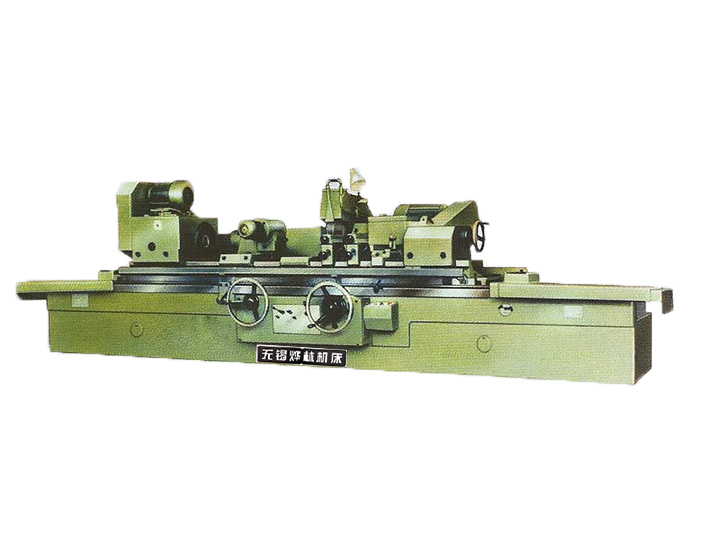
Crankshaft grinders are indispensable high-precision CNC machine tools in engine production lines, specifically designed for precision grinding of the main journals and connecting rod journals of crankshafts. By strictly controlling dimensional accuracy, geometric shape, and surface roughness, they ensure engines possess high power, low vibration, and long service life. Ordinary cylindrical grinders cannot meet the special structure and extremely high precision requirements of crankshafts, thus making crankshaft grinders key equipment for processing core engine components.
Core Structure and Working Principle
Crankshaft grinders consist of core components such as the bed, headstock and tailstock, grinding wheel headstock, synchronous fixtures, and CNC system. Their working principle is based on high-precision servo control: the headstock drives the crankshaft to rotate, and the synchronous fixture adjusts its position in real-time through electronic synchronization technology to ensure the eccentric connecting rod journal maintains the correct relative position with the grinding wheel. The in-line measurement system monitors dimensional data in real-time and feeds it back to the CNC system for automatic compensation, ensuring processing consistency.
Technical Advantages and Application Value
Crankshaft grinders have three major advantages: high precision (micron-level tolerance), high efficiency (automated loading and unloading), and high flexibility (multi-model adaptation). They support constant linear speed grinding technology, which automatically adjusts the grinding wheel speed according to the crankshaft position to ensure stable grinding force, significantly improving surface quality. In addition, the intelligent operation interface and modular design reduce operational difficulty and maintenance costs, helping enterprises achieve continuous and stable production.
Maintenance and Operation Specifications
To ensure long-term stable operation of the equipment, it is necessary to regularly inspect the lubrication system, fasten key components, and calibrate the measurement system. Operators need to be familiar with equipment performance and strictly follow the procedures: check the status of handles and travel stops before starting the machine, and lubricating oil according to specifications; monitor parameter abnormalities during processing and adjust the grinding program in a timely manner. Daily maintenance includes coolant replacement, grinding wheel dressing, and guide rail cleaning to extend equipment life and ensure processing accuracy.
Crankshaft grinders are a technical benchmark in high-end manufacturing, and their development level directly reflects a country’s strength in industrial fields such as automotive and marine. With the advancement of intelligent manufacturing, crankshaft grinders will further integrate data interconnection and adaptive control functions, providing core support for modern industry.
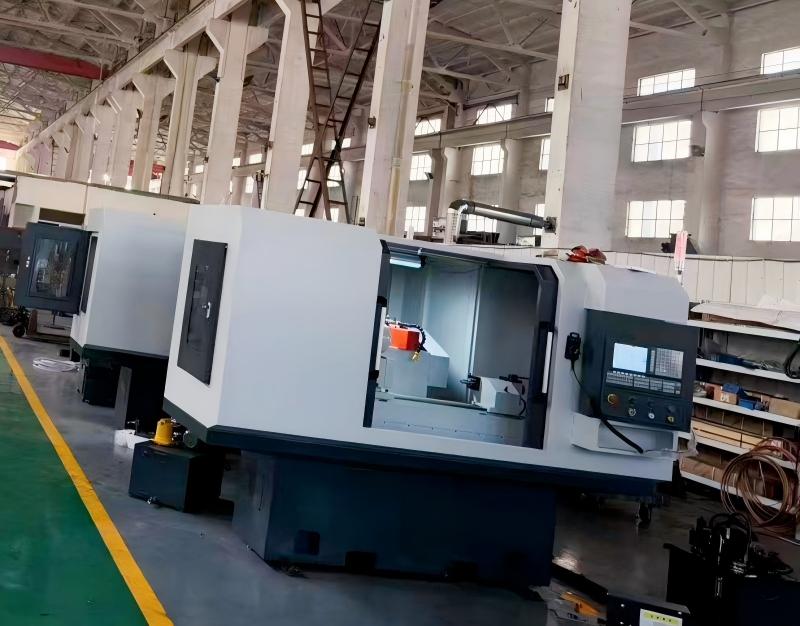
Uncompromising pre-shipment quality is a cornerstone of Yelin Machine Tools’ reputation. Before each CNC external cylindrical machine tool leaves the factory, Yelin’s engineers act as meticulous detail inspectors, conducting a thorough, step-by-step verification to eliminate all potential hazards—covering core mechanical, electrical and pneumatic systems.
The inspection starts with spindle operation—the core of CNC machines. Engineers monitor rotational stability, vibration amplitude and speed consistency under idle and simulated full-load conditions, using precision vibration analyzers to detect micro-irregularities. This ensures the spindle delivers sustained high-precision, low-noise performance in heavy-duty machining, where minor deviations affect workpiece accuracy and efficiency.
Next is axial system accuracy verification, a key performance indicator. With advanced laser interferometers and high-precision dial indicators, the team calibrates positional accuracy, repeatability and backlash of linear and rotary axes, adhering to tolerance standards that exceed industry benchmarks for long-term, high-frequency precision in high-end manufacturing.
Electrical and air path sealing integrity is also strictly verified for safety and durability. Pneumatic components undergo pressure retention tests to eliminate leakage risks, while electrical systems get insulation resistance and continuity tests to prevent faults in harsh workshop environments (high humidity, dust, voltage fluctuations).
Every detail—bolt torque, wiring, seal fittings—is cross-verified by multiple engineers and documented in a digital quality record. This traceable system strengthens accountability and provides customers full transparency into equipment quality.
Upholding these stringent standards and craftsmanship, Yelin builds a solid quality defense. Each inspected machine carries the brand’s pursuit of excellence, embodying craftsmanship and reliability to guarantee customers’ production efficiency, operational stability and long-term ROI.
Spiral duct, also known as spiral seamed duct, is a type of circular duct formed by spiral rolling and seaming of metal strips. Due to its excellent performance, it has become a mainstream product in ventilation, air conditioning, and dust removal systems. The following is an analysis of its core advantages, applicable scenarios, and key purchasing points from multiple dimensions.
I. Core Performance Advantages
The core advantages of spiral ducts lie in sealing, strength, economy, and installation efficiency. Its unique continuous spiral seaming structure ensures extremely high airtightness, significantly reducing air leakage rate and improving system energy efficiency. The circular design endows it with excellent strength and rigidity, effectively resisting pressure and preventing deformation. In terms of material usage, the circular cross-section has the shortest perimeter, saving approximately 20% of materials compared to rectangular ducts. The smooth inner wall significantly reduces fluid resistance, with a friction resistance coefficient as low as 0.011, achieving long-term energy savings during operation. During installation, its light weight and fewer connection points (commonly using clamp quick connections) greatly improve construction efficiency and shorten the project cycle. In addition, air flows smoothly in circular ducts, avoiding turbulence and corner vortices, thereby effectively reducing operating noise.
II. Wide Range of Application Fields
Spiral ducts have extremely wide applicability, covering almost all scenarios requiring air handling. In civil buildings, they are an ideal choice for central air conditioning supply and return air systems in office buildings, shopping malls, hotels, and hospitals. In the industrial sector, they are widely used in ventilation, dust removal, and smoke exhaust systems in factory workshops. Commercial kitchen fume extraction also frequently uses stainless steel spiral ducts to ensure corrosion resistance. Furthermore, ventilation systems in cleanrooms of pharmaceutical and electronics industries with extremely high cleanliness requirements also rely on their high sealing and low resistance characteristics.
III. Material Selection and Applicable Scenarios
Different materials meet diverse environmental and functional needs. Galvanized steel (GI) is the most economical and versatile choice, with good rust resistance, suitable for most ventilation and air conditioning environments. Stainless steel (SUS) provides extremely high corrosion and high-temperature resistance, making it a standard configuration for special occasions such as kitchen fume extraction, chemical industry, and pharmaceuticals. Aluminum alloy (AL) is lightweight, rust-resistant, and has decorative appearance, commonly used in projects sensitive to weight or requiring exposed installation aesthetics.
IV. Key Considerations for Purchasing
Multiple factors need to be comprehensively evaluated during purchasing to ensure project success. Material is the foundation, which should be determined based on the corrosiveness, temperature, and other conditions of the specific application environment. Thickness is directly related to the pressure-bearing capacity and durability of the pipeline, and should be selected according to the system design pressure. Dimensions need to strictly match the air volume and wind speed design requirements of the ventilation system. Choosing manufacturers with good reputation and rich experience is crucial to ensure product quality and reliability. Finally, under the condition of meeting all technical requirements, conduct a comprehensive cost comparison to select the product with the best cost performance.
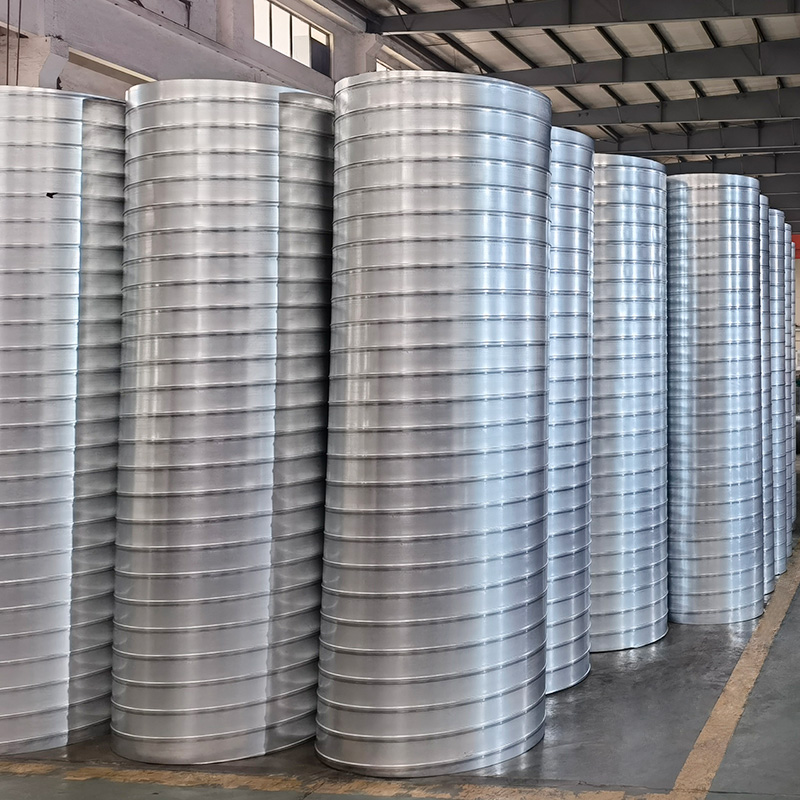
Stainless steel spiral air ducts are circular ventilation ducts made from high-quality stainless steel sheets using advanced spiral lock-forming technology. Due to their excellent corrosion resistance, high strength, and superior airtight performance, they are widely used in ventilation, smoke exhaust, and process piping systems with high requirements for cleanliness, corrosion resistance, or high temperature resistance.
In terms of sheet thickness and strength, the thickness of the air duct must be comprehensively determined based on the system’s working pressure and pipe diameter. High-pressure or negative-pressure systems have stricter requirements for sheet thickness. When the diameter or long-side dimension of the air duct is large, to meet the strength requirements for resisting high negative pressure, the length of a single section is usually required not to exceed 1 meter, the reinforcement spacing should be no more than 1 meter, and flange connections should be adopted to ensure the overall structure is stable and reliable.
The choice of connection technology depends on the sheet thickness. For sheets with a thickness of 1 mm or less, lock-seam or riveting is applicable; when exceeding 1 mm, argon arc welding must be used, and gas welding is strictly prohibited. The welding material must match the stainless steel base metal, and after welding, welding slag and spatter must be thoroughly cleaned to ensure a smooth inner wall. Especially in oil fume exhaust systems, the flange and the duct body must use full welding technology to achieve complete sealing.
If carbon steel flanges or fasteners are used, their surfaces must undergo anti-corrosion treatments such as chrome plating or galvanizing to prevent electrochemical corrosion and ensure the long-term operational stability and service life of the system.
Quality acceptance shall implement corresponding standards according to the system category. The allowable air leakage rate of metal circular air ducts is generally 50% of that of rectangular air ducts. During acceptance, product qualification certificates should be verified, and on-site re-inspection should be conducted if necessary to ensure that their strength and tightness meet the design requirements.
Stainless steel spiral air ducts have several significant advantages: excellent corrosion resistance, suitable for humid, corrosive gas, or high-cleanliness environments; high strength and long service life; smooth inner walls, low wind resistance, low operating energy consumption, and low noise; neat and beautiful appearance, easy to clean and maintain. They are an efficient and reliable ventilation duct solution.
Their design, production, and installation must strictly comply with relevant technical specifications to ensure safe, efficient, and long-term operation of the system, meeting various ventilation and exhaust needs.
Dust collection spiral ducts are core components of industrial ventilation and dust removal systems. Made using a spiral lockseam process with metal strips, they feature no welding, high sealing performance, and high strength. Suitable for environments with dust or harmful gases such as factory workshops and production sites, they are mainly used for efficient dust removal, air supply, exhaust, and material transportation.
Based on material differences, dust collection spiral ducts are mainly divided into three types: galvanized spiral ducts, stainless steel spiral ducts, and composite spiral ducts. Galvanized spiral ducts, with excellent rust resistance and high cost-effectiveness, have become the most widely used type in the market, especially suitable for environments with high humidity or weak corrosive gases, such as woodworking and food processing workshops. Stainless steel ducts offer stronger corrosion resistance and are suitable for special places with strong corrosion or high cleanliness requirements, but their cost is relatively higher. Composite ducts are mostly used in general environments with lower requirements.
In terms of performance, dust collection spiral ducts can withstand high wind pressure, meeting the usage needs of medium-low pressure and some high-pressure systems. Their smooth inner and outer walls result in low wind resistance, helping to reduce energy consumption and operational noise. Standardized production ensures high product consistency, enabling convenient installation. On-site adjustments such as cutting and can be performed, significantly shortening the construction period. After installation, frequent maintenance is usually not required, reducing long-term operating costs.
When selecting dust collection spiral ducts, it is necessary to comprehensively evaluate the environmental characteristics of the usage scenario. For working conditions with high temperatures (exceeding 60°C), high pressure, or high mechanical impact, consideration should be given to using carbon steel ducts with anti-corrosion treatment or directly selecting stainless steel materials. In extremely corrosive or high-temperature environments, upgrading to special materials such as stainless steel ducts or fiberglass ducts may be necessary.
If there are specific engineering parameters or special environmental requirements, it is recommended to provide detailed working condition information to facilitate more accurate selection and design suggestions.
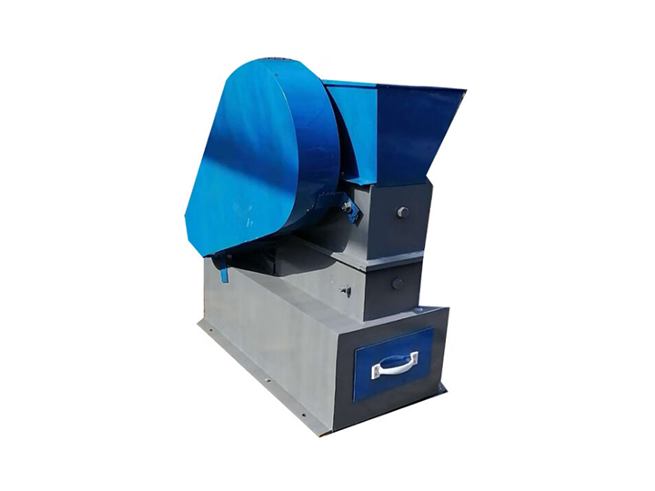
A crusher is a key equipment that uses mechanical force to break large solid materials into particles of desired size, widely used in industrial production, resource recycling, and daily processing. Its core principle is to destroy the internal bonding force of materials by applying external forces (such as impact, shear, extrusion, or grinding) to reduce particle size. The following explanation covers three aspects: working principles, type selection, and safe operation.
I. Working Principles
Crushers achieve material through mechanical energy conversion, with main methods including:
1. Impact crushing: High-speed rotating hammers or blades strike materials, suitable for brittle and hard materials.
2. Shear crushing: Using relatively moving blades to cut fibrous materials (e.g., paper, plastic).
3. Compression crushing: Applying pressure through two working surfaces to crush hard materials (e.g., ores).
4. Grinding crushing: Materials are frictionally peeled between grinding media into fine powder, suitable for ultra-fine powder preparation.
Equipment usually combines multiple methods and controls the discharge through screens, ensuring only particles of are discharged.
II. Types and Selection Guide
According to material characteristics and requirements, common crusher types include:
– Jaw crusher: Used for coarse crushing in mines, with large processing capacity and simple structure.
– Hammer/counterattack crusher: Suitable for medium and fine crushing, such as limestone or construction waste.
– Knife crusher: Specialized for waste treatment (e.g., plastic, wood) and resource recycling.
– Ball mill: Used for ultra-fine grinding in mining and chemical industries.
– Household kitchen waste crusher: Installed under kitchen sinks to handle food waste.
1. Protection preparation: Wear safety helmet, goggles, and tight work clothes; avoid long hair or clothing being.
2. Pre-start inspection: Confirm parts are fastened, no foreign objects in the cavity, and lubricate key parts.
3. Standard feeding: Prohibit putting in metals or hard objects to prevent damage to and equipment.
4. Operation taboos: It is strictly forbidden to open the protective cover or reach into the equipment while it is running.
5. Emergency measures: Familiarize with the location of the emergency stop button and immediately cut off power in case of abnormalities.
6. Regular maintenance: Replace worn parts (e.g., hammers, screens) to keep the equipment in good condition.
In conclusion, the efficient use of crushers depends on correct type selection and safe operation. In practical applications, schemes need to be refined based on material characteristics and production requirements to ensure equipment life and operation safety.
In recent years, the global manufacturing and fabrication sectors have witnessed an exponential surge in demand for precision engineering, high-speed production, and operational efficiency—drivers that have catalyzed the widespread adoption of computerized cutting technologies. These advanced systems have redefined the paradigms of material processing, offering unparalleled dimensional accuracy, process repeatability, and versatility across diverse industrial applications. However, amid a diverse array of solutions—ranging from CNC robotic beam cutting systems to 6-axis robotic 3D laser cutting cells—identifying the optimal computerized cutting machine requires a systematic evaluation of technical capabilities, industry-specific requirements, and operational constraints.
This comprehensive analysis delves into the technical nuances of computerized cutting machines, exploring their core functionalities, classification, and performance parameters. Whether you are a manufacturing professional seeking to upgrade legacy equipment, a plant manager evaluating automation solutions, or an industry newcomer navigating the technological landscape, this guide provides data-driven insights to facilitate informed decision-making.
Computerized cutting machines, formally referred to as Computer Numerical Control (CNC) cutting systems, are automated material processing tools that execute pre-programmed cutting trajectories via computer-aided design (CAD) and computer-aided manufacturing (CAM) software integration. By translating digital blueprints into precise mechanical movements, these systems eliminate the variability associated with manual cutting, ensuring consistent performance even for complex geometries. As integral components of modern manufacturing ecosystems, CNC cutting machines are deployed across automotive, aerospace, construction, metal fabrication, electronics, and jewelry industries, among others, owing to their ability to process a wide spectrum of materials—including ferrous and non-ferrous metals, polymers, composites, and ceramics—with exceptional precision.
Key Classifications of Computerized Cutting Machines
Computerized cutting machines are categorized based on their cutting mechanism, degrees of freedom, and application specificity. Below is a detailed breakdown of the most technologically advanced and industrially relevant types:
1. CNC Robotic Beam Cutting Systems
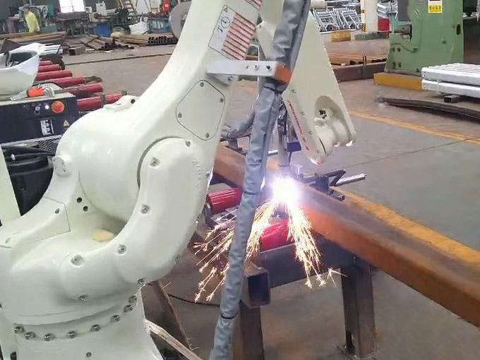
Engineered for heavy-duty structural processing, CNC robotic beam cutting systems integrate articulated robotic arms with high-power cutting tools (typically plasma or oxy-fuel) to process large-format beams, columns, and structural components. These systems excel in cutting H-beams, I-beams, and box sections made of carbon steel, stainless steel, and aluminum, with cutting thicknesses ranging from 10mm to 300mm and positional accuracy of ±0.2mm/m. Their robust design and automated material handling capabilities make them indispensable in construction, bridge building, and heavy machinery manufacturing, where high-volume processing of structural steel is a core operational requirement.
2. Plasma Robotic Cutting Systems
Plasma robotic cutting leverages a high-velocity jet of ionized gas (plasma) generated by an electric arc, which heats and melts conductive materials while expelling molten debris via gas pressure. This technology is distinguished by its high cutting speed (up to 500mm/min for 20mm steel) and ability to process thick materials (up to 150mm for carbon steel), making it ideal for industries such as shipbuilding, offshore engineering, and automotive chassis manufacturing. Modern plasma robotic systems incorporate advanced features such as automatic torch height control (ATHC) and plasma gas optimization, which enhance cut quality by minimizing kerf width (typically 2-5mm) and reducing thermal distortion.
3. 3D Robot Fiber Laser Cutting Machines
Fiber laser cutting systems represent the pinnacle of precision cutting technology, utilizing a high-energy fiber laser beam (wavelength: 1064nm) to ablate or melt materials with micron-level accuracy. These machines offer positional repeatability of ±0.03mm and are capable of processing thin to medium-thickness materials (0.1mm to 30mm for metals) with intricate geometries—making them the preferred choice for aerospace component manufacturing (e.g., turbine blades, aircraft fuselage panels), electronics (PCB cutting, micro-component fabrication), and medical device production. The fiber laser’s superior energy density (up to 10^6 W/cm²) ensures minimal heat-affected zones (HAZ), preserving material integrity and reducing post-processing requirements.
4. Laser Cutting Systems (CO₂ and Fiber)
Laser cutting systems are classified into CO₂ laser and fiber laser variants, each optimized for specific applications. CO₂ lasers (wavelength: 10.6μm) excel in cutting non-metallic materials such as acrylic, wood, and textiles, with cutting speeds up to 10m/min for thin sheets. Fiber laser systems, by contrast, are tailored for metallic materials, offering higher energy efficiency (up to 30% compared to CO₂ lasers) and lower operational costs. Both technologies are widely adopted in industries requiring high-quality edge finishes, such as jewelry manufacturing (precision metal stamping) and electronics (semiconductor wafer dicing).
5. Robotic Cutting Systems (Hybrid Configurations)
Robotic cutting systems combine the dexterity of multi-axis robotic arms (3-6 axes) with modular cutting tools (plasma, laser, or waterjet), enabling flexible processing of complex workpieces. These hybrid configurations are designed for adaptive manufacturing, where production runs require frequent tool changes or geometry adjustments. Key features include offline programming (OLP) software, collision avoidance systems, and integration with manufacturing execution systems (MES), making them suitable for small-batch production and custom fabrication.
6. 6-Axis Robotic 3D Laser Cutting Cells
As the most advanced category of computerized cutting machines, 6-axis robotic 3D laser cutting cells offer six degrees of freedom, enabling simultaneous movement along linear (X, Y, Z) and rotational (A, B, C) axes. This kinematic flexibility allows for cutting complex 3D contours, undercuts, and curved surfaces—critical for aerospace engine components, automotive body-in-white (BIW) structures, and composite material processing. Equipped with high-power fiber lasers (up to 15kW) and real-time vision systems, these cells achieve cutting accuracy of ±0.05mm and are capable of processing materials with hardness up to HRC 60, including titanium alloys and Inconel.
Critical Selection Criteria for Optimal Performance
The “best” computerized cutting machine is inherently application-specific, as no single system can excel across all use cases. Below are the key technical, operational, and economic factors to consider when evaluating solutions:
1. Material Compatibility and Thickness Range
The primary determinant of machine selection is the type and thickness of materials to be processed. For example:
– Thick metallic materials (≥50mm): Plasma robotic cutting systems or CNC oxy-fuel cutting machines offer the optimal balance of speed and cost-effectiveness.
– Thin metals (≤10mm) and intricate designs: 3D robot fiber laser cutting machines deliver superior precision and edge quality.
– Non-metallic materials (polymers, composites): CO₂ laser cutting systems or waterjet cutting machines are preferred to avoid thermal damage.
2. Dimensional Accuracy and Tolerance Requirements
Industries such as aerospace and medical device manufacturing demand ultra-tight tolerances (±0.01mm to ±0.1mm), making 6-axis robotic 3D laser cutting cells or high-precision fiber laser systems the ideal choice. For general metal fabrication (tolerances ±0.5mm), CNC robotic beam cutting or plasma systems provide sufficient accuracy at a lower cost point.
3. Production Volume and Cycle Time
High-volume manufacturing environments (e.g., automotive assembly lines) require systems with rapid cutting speeds and automated material handling. CNC robotic beam cutting systems (cycle time reduction of up to 40% vs. manual cutting) and plasma robotic cells are optimized for throughput, while 3D laser systems prioritize precision over raw speed.
4. Capital and Operational Costs
Advanced systems such as 6-axis robotic 3D laser cutting cells typically carry a higher initial investment (range: $200,000–$1,000,000) but offer lower operational costs due to energy efficiency and reduced material waste. Budget-constrained operations may opt for entry-level CNC plasma systems ($50,000–$150,000) or refurbished laser cutting machines, provided they meet performance requirements.
5. Automation Integration and Scalability
The level of automation required depends on production goals:
– Fully automated systems (e.g., 6-axis robotic cells with conveyor integration) reduce labor costs by up to 70% and enable 24/7 operation but require higher upfront investment.
– Semi-automated systems (e.g., standalone CNC laser cutters) are suitable for small-batch production, offering flexibility with lower capital expenditure.
– Scalability is another critical factor—systems with modular designs (e.g., robotic arms with interchangeable cutting tools) allow for future upgrades to accommodate evolving production needs.
6. Maintenance and Technical Support
Reliability and after-sales support are essential for minimizing downtime. Laser-based systems require periodic maintenance (e.g., lens cleaning, laser source calibration) every 500–1,000 operating hours, while plasma systems need electrode replacement every 100–200 hours. Choosing a supplier with a global service network and readily available spare parts is critical for long-term operational efficiency.
Core Advantages of Computerized Cutting Machines
The adoption of computerized cutting technology delivers transformative benefits to manufacturing operations, including:
1. Unmatched Precision and Repeatability
By eliminating human error and leveraging closed-loop feedback systems, CNC cutting machines achieve consistent dimensional accuracy across thousands of workpieces. This is particularly critical for industries with strict quality control standards (e.g., aerospace OEMs), where even minor deviations can compromise product performance.
2. Enhanced Production Efficiency
Automated cutting processes reduce cycle times by 30–60% compared to manual methods, enabling higher throughput and faster time-to-market. Additionally, features such as nest optimization software (which maximizes material utilization) and parallel processing capabilities further enhance operational efficiency.
3. Exceptional Versatility
Modern CNC cutting machines can process a wide range of materials and geometries, from simple 2D cuts to complex 3D contours. This versatility allows manufacturers to diversify their product portfolios without investing in multiple specialized tools.
4. Reduced Material Waste and Sustainability
Precision cutting minimizes material waste by up to 30% compared to manual methods, reducing raw material costs and environmental impact. Furthermore, energy-efficient technologies (e.g., fiber lasers) lower carbon emissions, aligning with global sustainability initiatives.
5. Improved Workplace Safety
Automated systems eliminate the need for operators to work in close proximity to cutting tools, reducing the risk of injuries associated with manual cutting (e.g., lacerations, thermal burns). Advanced safety features—such as interlocked enclosures, emergency stop buttons, and laser safety curtains—further enhance workplace safety.
Conclusion
The “best” computerized cutting machine is not a one-size-fits-all solution but rather a technology that aligns with your specific industrial requirements, performance parameters, and budget constraints. For heavy-duty structural processing, CNC robotic beam cutting systems and plasma robotic cells offer optimal speed and durability. For precision-critical applications in aerospace or electronics, 3D robot fiber laser cutting machines or 6-axis robotic 3D laser cutting cells deliver unmatched accuracy. For non-metallic materials, CO₂ laser or waterjet systems are the preferred choices.
When evaluating options, prioritize technical specifications such as material compatibility, tolerance capabilities, and automation features, while balancing these with long-term operational costs and scalability. By investing in the right computerized cutting machine, manufacturers can unlock significant productivity gains, improve product quality, and maintain a competitive edge in an increasingly demanding global market.
In the era of Industry 4.0, the integration of CNC cutting systems with IoT (Internet of Things) platforms, AI-driven predictive maintenance, and digital twin technology is poised to further revolutionize material processing—making continuous evaluation of technological advancements a critical component of long-term manufacturing success.
In the era of Industry 4.0, global manufacturing and supply chain ecosystems are undergoing a transformative shift toward automation, digitalization, and intelligent optimization. As the backbone of logistics automation, material handling robots—formally classified as Automated Material Handling Systems (AMHS)—have emerged as critical enablers of operational efficiency, process reliability, and supply chain resilience. These advanced robotic systems redefine the movement, storage, control, and protection of raw materials, work-in-progress (WIP), and finished goods across industrial facilities, warehouses, and distribution centers. By automating labor-intensive, repetitive, and high-risk material handling tasks, they not only address the limitations of manual operations but also unlock new levels of productivity, precision, and scalability for modern enterprises.
This article provides a technical exploration of material handling robots, covering their core definitions, classification, key technologies, performance benefits, industry applications, and emerging trends. Designed for manufacturing engineers, supply chain managers, and technology procurement professionals, this analysis aims to demystify the technical nuances of these systems while highlighting their strategic value in industrial automation.
Core Definition and Operational Scope
Material handling robots are programmable, automated systems engineered to execute material-centric tasks with minimal human intervention. Unlike general-purpose industrial robots, they are specialized for optimizing material flow—encompassing functions such as:
– Precision picking, placing, and sorting of components or finished products;
– Palletizing (stacking) and depalletizing (unstacking) of bulk goods;
– Intralogistics transportation between production lines, storage zones, and shipping docks;
– Automated storage and retrieval (AS/RS) within warehouses or distribution centers;
– Specialized handling of fragile, hazardous, or high-value materials (e.g., liquids, electronics, pharmaceuticals).
These robots integrate mechanical engineering, motion control, sensor technology, and software algorithms to adapt to dynamic industrial environments, ensuring consistent performance even in high-volume or complex operational scenarios. Their core value lies in streamlining material flow, reducing bottlenecks, and aligning material handling processes with lean manufacturing principles.
Classification of Material Handling Robots
Material handling robots are categorized based on their kinematic design, mobility, and application specificity. Below is a technical breakdown of the most industrially relevant types, including their operational principles, performance parameters, and use cases:
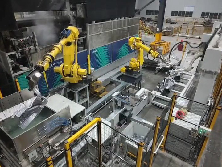
1. Articulated Material Handling Robots
Articulated robots are equipped with 4–6 rotational joints (axes) that mimic human arm movement, offering exceptional flexibility for complex material handling tasks. Typically mounted on fixed bases, they are optimized for high-precision picking, placing, and assembly operations in manufacturing environments.
– Integration with end effectors (grippers) for multi-material handling.
Typical Applications:
– Automotive manufacturing: Handling engine components, body panels, and fasteners during assembly;
– Electronics production: Precision placement of circuit boards, semiconductors, and delicate components;
– Consumer goods: Packaging and sorting of small-to-medium-sized products (e.g., smartphones, cosmetics).
2. Automated Guided Vehicles (AGVs)
AGVs are mobile robots that navigate predefined paths using guidance systems such as magnetic tapes, QR codes, or laser triangulation. They are designed for intralogistics transportation, moving heavy loads or bulk materials across warehouses, factories, or distribution centers.
– Safety features: Collision avoidance sensors, emergency stop systems, and compliance with ISO 15085.
Typical Applications:
– Warehouse operations: Transporting pallets, bins, and containers between storage racks and packing stations;
– Manufacturing: Delivering raw materials to production lines and removing finished goods to storage zones;
– Logistics: Loading and unloading goods from trucks and conveyor systems.
3. Autonomous Mobile Robots (AMRs)
AMRs represent the next generation of mobile material handling robots, leveraging advanced navigation technologies (LIDAR, computer vision, SLAM—Simultaneous Localization and Mapping) to navigate dynamically without predefined paths. They can adapt to changes in the environment (e.g., obstacles, rearranged storage racks) and optimize routes in real time.
– Integration with warehouse management systems (WMS) and manufacturing execution systems (MES).
Typical Applications:
– E-commerce fulfillment centers: Picking and transporting orders to packing stations (e.g., Amazon Robotics Kiva systems);
– Healthcare: Delivering medical supplies, medications, and equipment within hospitals;
– Retail: Restocking shelves and transporting inventory between backrooms and sales floors.
4. Automated Case-Handling Mobile Robots (ACMRs)
ACMRs are specialized mobile robots designed for handling case-sized loads (e.g., cardboard boxes, plastic crates) in high-throughput warehouse environments. They combine the mobility of AMRs with specialized lifting mechanisms to stack, transport, and sort cases efficiently.
Key Technical Specifications:
– Load capacity per case: 10kg–50kg;
– Stack height: Up to 2.5m;
– Throughput: 100–300 cases per hour;
– Compatibility with standard warehouse racking systems (e.g., selective racks, flow racks).
Typical Applications:
– Distribution centers: Sorting and transporting cases to shipping lanes;
– Food and beverage: Handling packaged products between production lines and storage;
– Retail logistics: Preparing store-ready shipments from regional distribution centers.
5. Gantry (Cartesian) Robots
Gantry robots operate along three linear axes (X, Y, Z) within a fixed workspace, offering high precision and load capacity for overhead material handling. They are commonly used in applications requiring repetitive, high-speed picking and placing over large areas.
Key Technical Specifications:
– Payload capacity: 1kg–10,000kg;
– Repeatability: ±0.02mm–±0.1mm;
– Workspace size: Up to 50m (X-axis), 10m (Y-axis), 3m (Z-axis);
– Speed: Up to 5m/s (linear movement).
Typical Applications:
– Warehouse AS/RS systems: Retrieving and storing pallets or bins from high racks;
– Automotive: Handling large components (e.g., windshields, seats) during assembly;
– Packaging: High-speed picking and placing of products into boxes or containers.
6. Liquid Handling Robots
Liquid handling robots are specialized systems designed for precise dispensing, mixing, and transferring of liquids in laboratory, pharmaceutical, and biotech environments. They ensure ultra-high precision and reproducibility, critical for scientific research and drug development.
Key Technical Specifications:
– Dispensing volume range: 0.1μL–1L;
– Precision: ±0.1%–±1% of dispensed volume;
– Throughput: Up to 10,000 samples per hour (high-throughput models);
– Compatibility with various liquid types (aqueous solutions, solvents, viscous fluids).
Typical Applications:
– Pharmaceutical research: Drug discovery and high-throughput screening;
– Clinical diagnostics: Sample preparation and analysis;
– Biotechnology: Cell culture media preparation and nucleic acid purification.
Key Technologies and Components
Material handling robots rely on a suite of advanced technologies and modular components to deliver precision, reliability, and adaptability. Below is a detailed breakdown of their core technical enablers:
1. Perception and Navigation Systems
Perception systems enable robots to interact with their environment, while navigation systems ensure accurate movement:
– LIDAR (Light Detection and Ranging): Creates 3D maps of the environment for obstacle avoidance and localization, with a range of up to 100m and angular resolution of 0.1°;
– Machine Vision: Uses cameras and image processing algorithms to identify objects, verify barcodes/QR codes, and ensure precise picking/placing (resolution up to 12MP, frame rate up to 60fps);
– SLAM Technology: Enables AMRs to build maps in unknown environments and localize themselves in real time, with positioning accuracy of ±5mm;
– Sensor Fusion: Integrates data from LIDAR, cameras, ultrasonic sensors, and inertial measurement units (IMUs) to enhance environmental awareness and reliability.
2. End Effectors (Grippers)
End effectors are the “hands” of material handling robots, customized to handle specific materials and shapes:
– Mechanical Grippers: Equipped with jaws (parallel, angular, or custom) for gripping solid objects, with clamping forces ranging from 1N to 10,000N;
– Vacuum Grippers: Use suction cups to handle flat or irregularly shaped objects (e.g., boxes, sheets of metal), with lifting capacities up to 500kg;
– Magnetic Grippers: Utilize electromagnets or permanent magnets to handle ferrous materials (e.g., steel plates, automotive parts), ideal for high-speed applications;
– Custom End Effectors: Designed for specialized tasks (e.g., liquid dispensing nozzles, soft grippers for fragile items like glassware or produce).
3. Control and Software Systems
Control systems serve as the “brain” of material handling robots, enabling task execution, optimization, and integration:
– Programmable Logic Controllers (PLCs): Execute low-level control tasks (e.g., motion control, sensor data processing) with response times of <1ms;
– Robot Operating Systems (ROS): Open-source or proprietary software frameworks for programming, simulation, and integration of robotic components;
– AI and Machine Learning Algorithms: Optimize path planning, predict maintenance needs, and adapt to dynamic environments (e.g., real-time route adjustment for AMRs);
– Integration Software: Interfaces with WMS, MES, and enterprise resource planning (ERP) systems to synchronize material handling with production and logistics workflows.
4. Motion Control Systems
Motion control systems ensure precise and smooth movement of robotic joints or mobile platforms:
– Servo Motors: Provide high torque and positional accuracy for articulated robots and gantry systems, with speed control resolution of 0.1rpm;
– Stepper Motors: Used in low-cost, low-speed applications (e.g., small AGVs), offering precise positioning without feedback;
– Drive Systems: Include gearboxes, belts, and linear actuators to transmit motion, with efficiency ratings of up to 98%.
Core Benefits of Material Handling Robots
The adoption of material handling robots delivers quantifiable technical, operational, and economic benefits to industrial enterprises:
1. Enhanced Productivity and Throughput
– 24/7 uninterrupted operation reduces downtime by up to 30% compared to manual labor;
– High-speed task execution (e.g., AMRs with speeds up to 2m/s, gantry robots with picking rates up to 1,000 cycles per hour) increases throughput by 50–100% in high-volume environments;
– Automated task prioritization and path optimization minimize idle time, ensuring optimal resource utilization.
2. Superior Precision and Consistency
– Repeatability of ±0.01mm–±0.1mm eliminates human error, reducing material waste by 15–25% in precision-critical applications;
– Consistent handling of materials ensures uniform product quality, particularly in industries such as electronics and pharmaceuticals where tolerances are tight (±0.1mm or less);
– Machine vision integration enables real-time quality checks during handling, further reducing defect rates.
3. Cost Reduction and Operational Efficiency
– Labor cost savings of 30–70% by automating repetitive tasks, with a typical return on investment (ROI) of 1–3 years for industrial-grade systems;
– Reduced material waste and damage (e.g., <1% damage rate for fragile items) lowers raw material and replacement costs;
– Energy-efficient designs (e.g., AMRs with low-power motors, regenerative braking) reduce operational energy consumption by 20–30% compared to traditional material handling equipment.
4. Improved Workplace Safety
– Elimination of human exposure to high-risk tasks (e.g., lifting heavy loads >25kg, handling hazardous materials, working in extreme temperatures) reduces work-related injuries by up to 80%;
– Compliance with safety standards (ISO 10218 for industrial robots, ANSI/UL 1740 for AGVs) ensures adherence to global occupational health and safety regulations;
– Collision avoidance sensors and emergency stop systems prevent accidents in dynamic industrial environments.
5. Scalability and Flexibility
– Modular design allows for easy expansion of robot fleets to accommodate growing production volumes;
– Quick programming and reconfiguration (e.g., teach pendant interfaces, offline programming software) enable adaptation to new products or processes in as little as 1–2 hours;
– Compatibility with multiple end effectors and material types supports diverse operational needs without significant hardware modifications.
Industry-Specific Applications
Material handling robots are tailored to address the unique requirements of diverse industries, with specialized designs and configurations:
1. Manufacturing
– Automotive: Articulated robots handle engine components, body panels, and fasteners during assembly; AGVs transport WIP between production lines;
– Electronics: Precision gantry robots place semiconductors and circuit boards; liquid handling robots dispense solder paste and adhesives;
– Aerospace: Heavy-duty articulated robots (payload >500kg) handle large structural components (e.g., wings, fuselages); AMRs transport tools and materials in cleanrooms.
2. Warehousing and Logistics
– E-commerce: AMRs and ACMRs optimize order fulfillment by picking and transporting items to packing stations, reducing order processing time by 40–60%;
– Retail Logistics: AGVs and AS/RS systems automate storage and retrieval of inventory, improving space utilization by 30–50%;
– Third-Party Logistics (3PL): Modular AMR fleets adapt to fluctuating order volumes, ensuring scalability during peak seasons.
3. Food and Beverage
– Processing: Hygienic-design robots (stainless steel construction, IP67 rating) handle raw materials and finished products, complying with FDA and EU food safety standards;
– Packaging: High-speed gantry robots palletize packaged goods, with throughput up to 300 cases per hour;
– Cold Chain: AMRs designed for low-temperature environments (-20°C to 0°C) transport frozen or refrigerated goods without performance degradation.
4. Healthcare and Pharmaceuticals
– Pharmaceuticals: Liquid handling robots dispense reagents and samples for drug discovery, ensuring precision and reproducibility; AGVs transport medications and medical supplies within cleanrooms;
– Hospitals: AMRs deliver linens, meals, and equipment, reducing staff workload and improving patient care efficiency;
– Biotechnology: High-throughput liquid handling robots support genomic sequencing and cell culture applications, with dispensing precision of ±0.1μL.
Challenges and Future Trends
While material handling robots offer significant benefits, their adoption is not without challenges. However, ongoing technological advancements are addressing these limitations and unlocking new possibilities:
Key Challenges
– High Initial Investment: Industrial-grade systems can cost $50,000–$500,000, posing a barrier for small and medium-sized enterprises (SMEs);
– System Integration Complexity: Integrating robots with legacy WMS/MES systems requires specialized expertise, potentially leading to delays or compatibility issues;
– Skills Gap: A shortage of trained engineers and technicians capable of programming, maintaining, and troubleshooting robotic systems hinders widespread adoption;
– Environmental Adaptability: Some robots struggle with harsh environments (e.g., dust, moisture, extreme temperatures) or unstructured spaces (e.g., cluttered warehouses).
Emerging Trends
– Collaborative Robots (Cobots): Designed for human-robot collaboration (HRC) under ISO/TS 15066, cobots feature force-torque sensors and safety-rated monitoring, enabling them to work alongside humans in tasks such as picking and packing;
– Digital Twin Technology: Virtual replicas of material handling systems simulate operations, allowing for offline programming, process optimization, and risk mitigation before deployment;
– IoT and Connectivity: Industrial IoT (IIoT) integration enables real-time monitoring of robot performance, fleet management, and data-driven decision-making; 5G connectivity supports low-latency communication between robots and central systems;
– Sustainability: Energy-efficient designs, recyclable materials, and battery technology advancements (e.g., lithium-ion batteries with 8-hour runtime) reduce the environmental footprint of robotic systems.