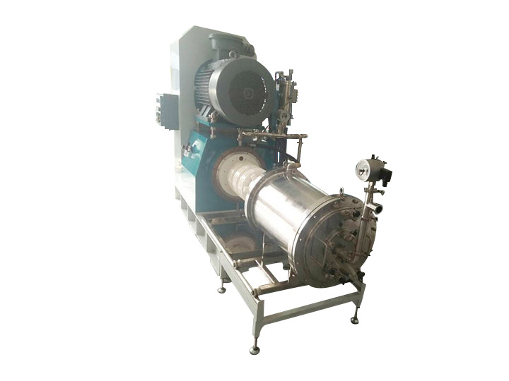
The Disc-Type Agitator Bead Mill (commonly known as the Disc Sand Mill or Disc Media Mill) stands as a cornerstone in the field of fine and ultra-fine grinding. Since the transition from traditional vertical sand mills to modern horizontal disc mills, this technology has become the gold standard for achieving sub-micron particle sizes in high-viscosity systems. It is indispensable in industries demanding high gloss, transparency, and stability, such as automotive coatings, printing inks, lithium-ion battery slurries, and premium ceramic pastes.
Mechanical Configuration and Core Components
A typical horizontal disc bead mill consists of a robust, pressure-resistant chamber through which the product flows. The key components defining its performance include:
• Grinding Chamber: Usually cylindrical, constructed from wear-resistant materials such as silicon carbide, zirconia, or tungsten carbide. Volumes range from laboratory scale (0.5 L) to industrial production scale (500+ L).
• Disc Agitator System: The heart of the machine. A rotating shaft equipped with multiple discs (flat, perforated, or profiled) spaced along its length. These discs create turbulent flow fields to accelerate the grinding media.
• Separation System: A critical interface at the discharge end. Modern mills utilize dynamic gap separators or centrifugal screens (slot sizes often 0.1–0.3 mm) to retain the grinding media while allowing the finished product to pass.
• Cooling System: Jacketed chambers and internally cooled rotors are essential to dissipate the significant heat generated by friction and impact during nano-grinding.
Grinding Mechanism and Energy Transfer
The comminution process in a disc mill is governed by the principles of stress intensity and stress frequency.
• Motion Patterns: As the shaft rotates, the discs impart kinetic energy to the grinding media (beads) and the slurry. The relative motion between the moving discs and the stationary chamber wall creates a complex three-dimensional flow.
1. Impact: Collision between beads accelerated by the agitator.
2. Compression: Squeezing of particles between two contacting beads.
3. Shear: Relative movement of beads causing laminar flow gradients in the slurry.
• Energy Density (kW/L): This is the most critical metric for disc mills. It defines the installed power relative to the grinding chamber volume. High-energy density mills (> 1.0 kW/L) are capable of true nano-grinding (D90 < 100 nm), whereas lower density mills are suited for micronization.
Disc Design Evolution and Hydrodynamics
The geometry of the discs significantly influences the flow profile and grinding efficiency:
• Standard Flat Discs: Create high shear zones near the disc edges but can suffer from dead zones in the center.
• Perforated or Turbulent Discs: Feature holes or profiles that force media recirculation. This design breaks up laminar layers and increases the frequency of stress events, leading to narrower particle size distributions (PSD).
• Segmented Discs: Offer higher flow rates and are better suited for high-viscosity products by preventing channeling.
Process Control and Operational Parameters
Optimizing a disc bead milling process requires precise control over several interdependent variables:
• Grinding Media Selection: The choice of bead material (zirconium silicate, yttrium-stabilized zirconia, cerium zirconia) and size is crucial. Smaller beads (0.1–0.8 mm) provide a higher surface area for contact and are necessary for nano-grinding, but require higher centrifugal forces for separation.
• Tip Speed: Typically maintained between 8–16 m/s. Higher speeds increase stress intensity but also generate more heat and wear.
• Specific Energy (kWh/t): The amount of energy consumed per ton of product is a direct indicator of grinding efficiency. Monitoring this helps in scaling up from lab trials to production.
• Cooling Capacity: Effective temperature control (maintaining product temperature below 50°C) is vital to prevent solvent evaporation, resin softening, or product degradation.
Comparison: Disc Mill vs. Other Agitator Designs
While pin mills and peg mills excel in specific areas, disc mills maintain a dominant position for certain applications.
Feature Disc Mill Pin Mill / Peg Mill Notes
Wear Pattern Even wear on disc surfaces; easy replacement. Localized wear on pins; complex replacement. Disc mills generally have lower maintenance costs.
Flow Profile Strong axial mixing; good for narrow PSD. More radial flow; higher shear peaks. Pin mills are often preferred for high-viscosity pre-dispersing.
Media Size Compatible with very small media (0.1 mm). Requires larger media due to pin spacing. Disc mills are superior for sub-micron grinding.
Industrial Applications
• Automotive Coatings: Grinding pigments to achieve high jetness (blackness) and brilliance in metallic basecoats.
• Battery Manufacturing: Dispersion of cathode (NCM, LFP) and anode (graphite, silicon) materials to ensure electrical conductivity and cycle life.
• Digital Printing Inks: Producing inks with particle sizes smaller than the nozzle diameter to prevent printhead clogging.
• Pharmaceuticals: Nano-crystallization of poorly soluble drugs to enhance bioavailability.
Maintenance, Wear, and Contamination Control
Due to the high-energy environment, wear management is a major concern:
• Abrasive Wear: Grinding highly filled mineral slurries (e.g., calcium carbonate, titanium dioxide) causes rapid wear of the discs and chamber liners. Regular measurement of gap clearances is required.
• Metal Contamination: For high-purity applications (e.g., battery materials), non-metallic liners and ceramic components are mandatory to prevent iron pickup, which can affect electrochemical performance.
• Cleaning-in-Place (CIP): Automated washing cycles with solvent or cleaning agents are essential to prevent cross-contamination between batches.
Future Trends and Innovations
The evolution of disc bead mills is focused on sustainability and intelligence:
• Smart Milling: Integration of real-time PSD analyzers (laser diffraction) and viscosity sensors to enable closed-loop control of the grinding process.
• Energy Recovery: Systems to capture and reuse the heat generated during grinding.
• Advanced Ceramics: Development of new ceramic composites for discs and chambers that offer higher fracture toughness and longer lifespans in aggressive environments.
Conclusion
The disc-type agitator bead mill remains a highly efficient and versatile solution for the most demanding dispersion tasks. By mastering the interplay between disc geometry, energy density, and process control, engineers can reliably produce nano-particle slurries that define the performance of next-generation materials.
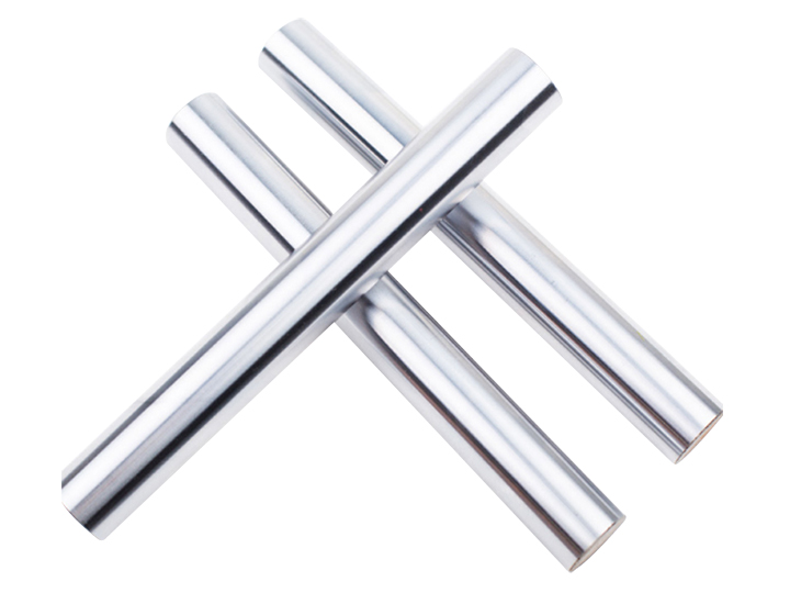
Choosing the right material for your piston rod is critical for performance and service life. The most common materials used for hydraulic piston rods are:
Carbon Steel (CK45, 45)
This is the most common material for general-purpose hydraulic piston rods. CK45 carbon steel offers good mechanical properties, excellent machinability, and is cost-effective. It’s suitable for most industrial hydraulic applications where corrosion isn’t extreme.
Alloy Steel (40Cr, 42CrMo)
Alloy steels provide higher strength and better toughness compared to plain carbon steel. They’re ideal for high-pressure applications and heavy-duty machinery where higher mechanical performance is required.
The main downside is higher cost compared to carbon steel.
Quenched and Tempered Steel
Quenching and tempering heat treatment improves the mechanical properties of the steel, increasing strength and toughness. This treatment is recommended for heavy-duty applications where higher mechanical performance is needed.
Choosing the right material depends on your application environment, pressure requirements, and budget. If you’re unsure which material is best for your project, contact Xinluo Hydraulic — our engineers can recommend the optimal material specification based on your requirements.
In the context of global energy conservation and carbon reduction, and the continuous upgrading of industrial equipment, heat exchange systems, as key components of energy conversion and utilization, are facing higher requirements for efficiency, compactness, and energy saving. Traditional smooth tube heat transfer elements have the disadvantages of small heat transfer area, low convective heat transfer coefficient, and large space occupation, which are difficult to meet the heat exchange needs of high-power, miniaturized, and high-efficiency equipment in modern industry.
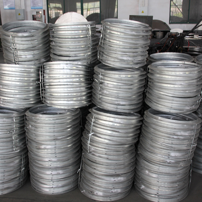
Gilled tubes, as an improved high-efficiency heat transfer element, realize the expansion of heat transfer area by adding fins on the surface of the base tube, while optimizing the flow field of the heat exchange medium, thereby significantly improving the overall heat transfer efficiency of the heat exchanger. Compared with traditional smooth tubes, under the same heat transfer load, gilled tubes can reduce the volume of the heat exchanger by 30% to 60%, reduce the consumption of metal materials, and save energy consumption by 15% to 25%, which has significant economic and environmental benefits.
The development of gilled tube technology is closely related to the progress of manufacturing processes and material science. From the early manual embedding fins to the modern automatic rolling, welding, and extrusion processes, the manufacturing precision, structural stability, and heat transfer performance of gilled tubes have been significantly improved. Today, gilled tubes have become indispensable core components in heat exchange systems such as industrial boilers, air conditioners, refrigerators, waste heat recovery equipment, and aerospace thermal control systems, covering thermal power generation, metallurgy, petrochemical, refrigeration and air conditioning, and other industries.
However, in the production and application of gilled tubes, there are still problems such as poor fin-base tube bonding strength, uneven fin distribution, corrosion of fin surfaces, and fouling, which affect the heat transfer efficiency and service life of gilled tubes. To give full play to the advantages of gilled tubes in high-efficiency heat transfer, it is necessary to deeply understand their manufacturing processes, clarify their application characteristics, and master the key technologies of production quality control and operation and maintenance. This paper focuses on the core of gilled tubes, systematically elaborates on their manufacturing processes, application advantages, application cases, and optimization measures, aiming to provide professional technical support for the efficient and stable operation of heat exchange systems.
2. Classification and Basic Structure of Gilled Tubes
Gilled tubes can be classified into different types according to their fin structure, manufacturing process, and application scenarios, and their basic structures are closely related to their heat transfer performance and application fields. A clear understanding of the classification and structure of gilled tubes is the basis for grasping their manufacturing processes and application advantages.
2.1 Classification of Gilled Tubes
Gilled tubes are mainly classified according to fin structure, manufacturing process, and material, and each type has distinct characteristics and applicable fields:
– Classification by Fin Structure: According to the arrangement form and shape of fins, gilled tubes are divided into spiral gilled tubes, longitudinal gilled tubes, and annular gilled tubes. Spiral gilled tubes have fins arranged in a spiral shape on the base tube, which can enhance the turbulence of the heat exchange medium, reduce fouling, and are widely used in boiler economizers, air preheaters, and waste heat recovery equipment. Longitudinal gilled tubes have fins arranged parallel to the axis of the base tube, which have low flow resistance and are suitable for scenarios with high medium flow rate, such as aerospace engine cooling and large-scale industrial heat exchangers. Annular gilled tubes have fins arranged in a circular ring shape perpendicular to the axis of the base tube, which are easy to manufacture and are suitable for small and medium-sized heat exchangers.
– Classification by Manufacturing Process: According to the manufacturing method of fins and base tube combination, gilled tubes are divided into embedded gilled tubes, welded gilled tubes, rolled gilled tubes, and extruded gilled tubes. Embedded gilled tubes are made by embedding fins into the grooves of the base tube, with high bonding strength and good heat transfer performance, suitable for high-temperature and high-pressure scenarios. Welded gilled tubes are made by welding fins to the surface of the base tube, with simple manufacturing process and low cost, suitable for medium and low temperature scenarios. Rolled gilled tubes are made by rolling fins on the surface of the base tube through a rolling process, with compact structure and high production efficiency, which is the most widely used type currently. Extruded gilled tubes are made by extruding the base tube material to form fins, with good integrity and corrosion resistance, suitable for corrosion-prone environments.
– Classification by Material: According to the material of the base tube and fins, gilled tubes are divided into carbon steel gilled tubes, alloy steel gilled tubes, copper gilled tubes, aluminum gilled tubes, and stainless steel gilled tubes. Carbon steel gilled tubes are low-cost and suitable for ordinary industrial scenarios with low corrosion requirements. Alloy steel gilled tubes have high temperature resistance and pressure-bearing capacity, suitable for high-temperature and high-pressure heat exchange systems such as boilers. Copper and aluminum gilled tubes have high thermal conductivity, suitable for refrigeration and air conditioning systems with high heat transfer efficiency requirements. Stainless steel gilled tubes have excellent corrosion resistance, suitable for corrosive medium scenarios such as petrochemical and marine equipment.
2.2 Basic Structure of Gilled Tubes
The basic structure of a typical gilled tube consists of two core components: a base tube and fins (gills), and the rationality of the structure directly affects the heat transfer performance and structural stability of the gilled tube:
– Base Tube: The core bearing component of the gilled tube, responsible for supporting the fins and conveying the internal heat exchange medium. The base tube is usually made of seamless steel pipe, copper pipe, aluminum pipe, or stainless steel pipe, with a diameter of 10mm to 100mm and a wall thickness of 1mm to 10mm, depending on the operating pressure, temperature, and medium characteristics. The surface of the base tube is usually processed with grooves, convex ribs, or rough surfaces to enhance the bonding strength between the base tube and fins and improve the heat transfer efficiency between them.
– Fins (Gills): The key component for expanding the heat transfer area, attached to the outer surface (or inner surface) of the base tube. The fins are usually made of materials with high thermal conductivity, such as copper, aluminum, carbon steel, and alloy steel, with a thickness of 0.1mm to 2mm, a height of 5mm to 50mm, and a pitch of 2mm to 20mm. The fin shape can be rectangular, triangular, serrated, or corrugated—serrated and corrugated fins can enhance the turbulence of the medium, further improving the convective heat transfer coefficient. For embedded and rolled gilled tubes, the fins are closely combined with the base tube to ensure efficient heat transfer; for welded gilled tubes, the welding seam between the fins and the base tube must be tight to avoid heat transfer resistance caused by gaps.
– Accessories: In practical applications, gilled tubes are usually equipped with additional structures to improve performance, such as anti-corrosion coatings (to enhance corrosion resistance), anti-fouling coatings (to reduce fouling), and reinforcing rings (to improve structural stability). For gilled tubes used in high-temperature and high-pressure environments, thermal insulation layers are also added to reduce heat loss.
The overall structure of the gilled tube is designed according to the heat exchange requirements, medium characteristics, and operating conditions. For example, in boiler economizers, spiral gilled tubes with large fin height and small pitch are usually used to maximize the heat transfer area; in refrigeration systems, copper or aluminum gilled tubes with thin fins and dense arrangement are used to improve heat transfer efficiency and reduce space occupation.
3. Key Manufacturing Processes of Gilled Tubes: Principle and Quality Control
The manufacturing process of gilled tubes is the core factor affecting their heat transfer performance, structural stability, and service life. Different manufacturing processes have their own characteristics, applicable scenarios, and quality control points. This section focuses on the four most common manufacturing processes of gilled tubes: embedding, welding, rolling, and extrusion, and elaborates on their process principles, technical characteristics, and quality control requirements.
3.1 Embedding Process (Embedded Gilled Tubes)
The embedding process is a high-precision manufacturing process that embeds fins into the pre-processed grooves of the base tube, relying on the interference fit or elastic deformation between the fins and the grooves to realize tight combination. This process is suitable for high-temperature, high-pressure, and high-vibration scenarios, such as boiler superheaters and aerospace engine heat exchangers.
Process Principle: First, process axial or spiral grooves on the outer surface of the base tube (the cross-section of the groove is usually dovetail-shaped or trapezoidal to enhance the bonding force); then, process the fins into a shape matching the groove, and embed the fins into the groove through mechanical extrusion or thermal expansion. During the embedding process, the fins are elastically deformed, and the base tube groove is slightly expanded, forming a tight interference fit between the two, ensuring no gap between the fin and the base tube, and realizing efficient heat transfer.
Technical Characteristics: The embedded gilled tube has high bonding strength between the fin and the base tube, good heat transfer performance (no gap heat resistance), and strong structural stability, which can withstand high temperature, high pressure, and high vibration. However, the process is complex, the manufacturing precision is high, the production efficiency is low, and the cost is relatively high.
Quality Control Points: Strictly control the size and shape of the base tube groove (groove width, depth, and angle) to ensure that it matches the fin; control the embedding force and speed to avoid fin damage or insufficient embedding; check the bonding tightness between the fin and the base tube after embedding, and eliminate gaps or loose combinations; detect the dimensional accuracy of the gilled tube (fin height, pitch, and straightness) to meet the design requirements.
3.2 Welding Process (Welded Gilled Tubes)
The welding process is the most widely used manufacturing process for gilled tubes, which welds the fins to the surface of the base tube through various welding methods, realizing the combination of the two. This process is suitable for medium and low temperature, medium and low pressure scenarios, such as air conditioners, refrigerators, and ordinary industrial heat exchangers.
Process Principle: First, clean the surface of the base tube and fins to remove oil, rust, and oxide layers to ensure welding quality; then, place the fins on the preset position of the base tube, and use welding methods such as resistance welding, argon arc welding, laser welding, or brazing to weld the fins to the base tube. The welding process melts the contact surface between the fin and the base tube, forming a welding seam, and after cooling, the two are firmly combined.
Technical Characteristics: The welding process has simple equipment, high production efficiency, low cost, and strong adaptability to different materials and fin structures. However, the bonding strength is lower than that of embedded gilled tubes, and there may be gaps or welding defects (such as pores, cracks) at the welding seam, which will increase the heat transfer resistance and affect the heat transfer efficiency. In addition, the welding seam is prone to corrosion in corrosive environments.
Quality Control Points: Select appropriate welding methods and welding parameters (welding current, voltage, speed) according to the material of the base tube and fins; strictly control the welding seam quality, avoid pores, cracks, and incomplete fusion; check the bonding strength of the welding seam through tensile tests; perform anti-corrosion treatment on the welding seam (such as painting, galvanizing) to enhance corrosion resistance.
3.3 Rolling Process (Rolled Gilled Tubes)
The rolling process is a continuous forming process that uses rolling tools to extrude the surface of the base tube, making the base tube material flow and form fins. This process is suitable for large-scale mass production, and is widely used in boiler economizers, air preheaters, and waste heat recovery equipment.
Process Principle: The base tube is clamped by a rolling machine and rotated at a certain speed; the rolling tool (with a fin-shaped groove) is pressed against the surface of the base tube, and the base tube material is extruded and flowed into the groove of the rolling tool, forming spiral or longitudinal fins. The rolling process is continuous, and the fin height, pitch, and shape can be adjusted by changing the rolling tool and rolling parameters.
Technical Characteristics: The rolled gilled tube has compact structure, uniform fin distribution, high production efficiency, and low cost. The fin and the base tube are integrated (no welding seam or gap), so the heat transfer efficiency is high, and the structural stability is good. However, the rolling process has high requirements on the ductility of the base tube material, and it is not suitable for brittle materials; the fin height is limited (usually not more than 30mm), and it is difficult to manufacture gilled tubes with large fin height.
Quality Control Points: Control the rolling speed, pressure, and temperature to ensure the fin shape and dimensional accuracy; check the fin height, pitch, and thickness to meet the design requirements; detect the surface quality of the fins, avoid scratches, cracks, and uneven thickness; check the straightness of the gilled tube to prevent deformation during rolling.
3.4 Extrusion Process (Extruded Gilled Tubes)
The extrusion process is a forming process that uses an extruder to extrude the base tube material through a die with a fin shape, directly forming fins on the surface of the base tube. This process is suitable for materials with good ductility (such as aluminum, copper), and is widely used in refrigeration and air conditioning systems.
Process Principle: The base tube blank is heated to a certain temperature (to improve ductility), and then pushed into the extrusion die by the extruder. The die has a cavity matching the shape of the gilled tube (base tube + fins), and the base tube blank is extruded through the die, forming fins on the surface while forming the base tube. The extrusion process can realize one-time forming of the gilled tube, with high integrity.
Technical Characteristics: The extruded gilled tube has good integrity, no gaps between the fin and the base tube, high heat transfer efficiency, and excellent corrosion resistance. The fin shape can be designed flexibly, and the production process is clean and environmentally friendly. However, the extrusion process requires high equipment investment, high energy consumption, and is only suitable for small and medium-sized gilled tubes; the material is limited to ductile metals such as aluminum and copper.
Quality Control Points: Control the extrusion temperature, speed, and pressure to ensure the fin shape and dimensional accuracy; check the surface quality of the gilled tube, avoid scratches, cracks, and uneven thickness; detect the mechanical properties of the gilled tube (tensile strength, ductility) to meet the application requirements; control the straightness and roundness of the gilled tube.
4. Core Application Advantages of Gilled Tubes: Key to High-Efficiency Heat Transfer
Gilled tubes, as high-efficiency heat transfer elements, have multiple core advantages compared with traditional smooth tubes, which not only can significantly improve the heat transfer efficiency of heat exchange systems, but also can save space, reduce energy consumption, and enhance operational stability. These advantages make gilled tubes an indispensable core component in modern heat exchange systems.
4.1 Significantly Improve Heat Transfer Efficiency
Improving heat transfer efficiency is the most core advantage of gilled tubes. The heat transfer efficiency of heat exchange elements is mainly determined by the heat transfer area and the convective heat transfer coefficient. Gilled tubes expand the heat transfer area by adding fins on the surface of the base tube—compared with smooth tubes of the same length and diameter, the heat transfer area of gilled tubes can be increased by 3 to 10 times, and even higher for gilled tubes with large fin height and dense arrangement.
At the same time, the fins can enhance the turbulence of the external heat exchange medium (such as flue gas, air), reduce the thickness of the boundary layer, and improve the convective heat transfer coefficient. For example, spiral gilled tubes can make the medium flow in a spiral direction, enhance the disturbance of the medium, and further improve the heat transfer efficiency. It is estimated that under the same working conditions, the heat transfer efficiency of gilled tubes is 2 to 5 times that of smooth tubes, which can significantly reduce the heat exchange area required for the same heat transfer load.
4.2 Save Space and Reduce Material Consumption
Against the background of the miniaturization of industrial equipment, the space occupation of heat exchange systems is increasingly restricted. Gilled tubes, with their high heat transfer efficiency, can achieve the same heat transfer load with a smaller heat exchange area, thereby reducing the volume and weight of the heat exchanger. Compared with heat exchangers using smooth tubes, the volume of heat exchangers using gilled tubes can be reduced by 30% to 60%, and the weight can be reduced by 20% to 50%.
In addition, the reduction of the heat exchange area also reduces the consumption of metal materials (base tube and fins), which not only reduces the manufacturing cost of the heat exchanger, but also saves valuable metal resources. For example, a boiler economizer using spiral gilled tubes can save 30% to 40% of steel compared with a smooth tube economizer of the same heat transfer capacity, which has significant economic benefits.
4.3 Reduce Energy Consumption and Operating Costs
The high heat transfer efficiency of gilled tubes can directly reduce the energy consumption of heat exchange systems, thereby reducing operating costs. For heat exchange systems that require power to drive the medium flow (such as fans, pumps), the use of gilled tubes can reduce the flow rate of the medium under the same heat transfer load, thereby reducing the power consumption of fans and pumps.
Taking a large industrial boiler economizer as an example, replacing smooth tubes with spiral gilled tubes can reduce the flue gas flow rate by 20% to 30%, thereby reducing the power consumption of the induced draft fan by 15% to 25%. For refrigeration and air conditioning systems, the use of gilled tubes can improve the heat exchange efficiency of the condenser and evaporator, reduce the energy consumption of the compressor, and reduce the annual operating cost by 10% to 20%.
4.4 Strong Adaptability to Working Conditions
Gilled tubes have strong adaptability to different working conditions, and can be customized according to the operating temperature, pressure, medium characteristics, and heat transfer requirements. For high-temperature and high-pressure scenarios (such as boiler superheaters), embedded or rolled gilled tubes made of alloy steel can be used; for corrosive medium scenarios (such as petrochemical equipment), stainless steel or anti-corrosion coated gilled tubes can be used; for low-temperature scenarios (such as refrigeration systems), copper or aluminum gilled tubes with high thermal conductivity can be used.
In addition, gilled tubes can be designed into different fin structures (spiral, longitudinal, annular) and sizes according to the flow characteristics of the medium, optimizing the flow field and further improving the heat transfer efficiency and operational stability. For example, in scenarios with high medium flow rate, longitudinal gilled tubes with low flow resistance are used; in scenarios with easy fouling, serrated gilled tubes that are easy to clean are used.
4.5 Long Service Life and High Reliability
Gilled tubes have high structural stability and long service life, especially embedded and rolled gilled tubes—since the fin and the base tube are tightly combined (no gaps or welding seams), they are not easy to fall off or damage, and can withstand high temperature, high pressure, and high vibration. The service life of gilled tubes is usually 8 to 15 years, which is longer than that of traditional smooth tubes (5 to 10 years).
In addition, gilled tubes are easy to maintain—for fouled gilled tubes, ash cleaning devices (such as soot blowers) can be used to clean the fins, restoring heat transfer efficiency; for damaged fins, local replacement or repair can be carried out without replacing the entire gilled tube, reducing maintenance costs and downtime.
5. Practical Application Cases and Effect Analysis
To further illustrate the application effect and core advantages of gilled tubes, this section selects typical application cases in boiler systems, refrigeration equipment, and waste heat recovery, and analyzes the heat transfer effect, energy-saving benefits, and economic benefits of gilled tubes.
5.1 Case 1: Boiler Economizer Gilled Tube Application
A 300MW coal-fired thermal power plant uses a subcritical boiler, and the original economizer adopts smooth tube heat exchange elements, with a flue gas inlet temperature of 420℃, an outlet temperature of 170℃, and a heat transfer efficiency of 85%. To improve heat transfer efficiency and reduce energy consumption, the plant replaced the smooth tube economizer with spiral rolled gilled tubes (base tube material: 20G carbon steel, fin material: Q235 carbon steel, fin height: 15mm, fin pitch: 10mm).
After the transformation, the heat transfer area of the economizer is increased by 4 times, the flue gas outlet temperature is reduced to 130℃, the heat transfer efficiency is increased to 92%, and the coal consumption per unit power generation is reduced by 8g/kWh. Based on the annual power generation of 1.8×10⁹ kWh, the annual coal saving is 14,400 tons, the annual economic benefit is about 7.2 million yuan (based on 500 yuan per ton of coal), and the annual CO₂ emission reduction is about 38,880 tons, achieving significant energy-saving, emission-reduction, and economic benefits.
5.2 Case 2: Refrigeration Air Conditioning Gilled Tube Application
A large shopping mall uses a central air conditioning system, and the original condenser adopts smooth copper tubes, with a heat transfer efficiency of 80%, a condenser volume of 12m³, and an annual power consumption of 1.2×10⁶ kWh. To reduce the volume of the condenser and save energy consumption, the mall replaced the smooth copper tubes with extruded aluminum gilled tubes (base tube material: copper, fin material: aluminum, fin height: 8mm, fin pitch: 5mm).
After the replacement, the heat transfer efficiency of the condenser is increased to 90%, the volume of the condenser is reduced to 5m³ (reduced by 58.3%), and the annual power consumption of the air conditioning system is reduced to 9.6×10⁵ kWh (reduced by 20%). The annual electricity saving is 2.4×10⁵ kWh, the annual economic benefit is about 192,000 yuan (based on 0.8 yuan/kWh), and the space occupation of the air conditioning system is significantly reduced, creating more usable space for the shopping mall.
5.3 Case 3: Industrial Waste Heat Recovery Gilled Tube Application
A petrochemical enterprise has a waste heat flue gas with a temperature of 350℃ and a flow rate of 50,000 m³/h, which was directly discharged in the past, resulting in massive energy waste. The enterprise installed a waste heat recovery heat exchanger using embedded alloy steel gilled tubes (base tube material: 12Cr1MoV alloy steel, fin material: 12Cr1MoV alloy steel, fin height: 20mm, fin pitch: 12mm) to recover the waste heat of the flue gas to heat the production water.
After the installation, the flue gas outlet temperature is reduced to 140℃, the waste heat recovery capacity is 12,000 kW, and the production water temperature is increased from 25℃ to 120℃. The annual waste heat recovery is about 1.05×10⁸ kWh, which can replace 42,000 tons of standard coal per year, save about 21 million yuan in fuel costs, and reduce CO₂ emissions by about 113,400 tons per year, achieving significant energy-saving and environmental protection benefits.
6. Common Quality Problems and Improvement Measures of Gilled Tubes
Although gilled tubes have the advantages of high heat transfer efficiency, long service life, and strong adaptability, they still face some common quality problems in production and application, such as poor fin-base tube bonding, fin damage, corrosion, and fouling, which affect their heat transfer performance and service life. This section analyzes these common problems and proposes corresponding improvement measures.
6.1 Common Quality Problems
– Poor Fin-Base Tube Bonding: This is the most common quality problem of gilled tubes, which is manifested as gaps between the fin and the base tube, or loose combination. For welded gilled tubes, it is mainly caused by welding defects (pores, cracks, incomplete fusion); for embedded and rolled gilled tubes, it is mainly caused by inaccurate dimensional matching or improper process parameters. Poor bonding will increase the gap heat resistance, significantly reduce the heat transfer efficiency, and even lead to fin falling off in high-vibration scenarios.
– Fin Damage: During the manufacturing, transportation, or installation process, the fins are easily scratched, bent, or broken, especially thin fins (thickness < 0.5mm). Fin damage will reduce the effective heat transfer area, affect the flow field of the medium, and reduce the heat transfer efficiency of the gilled tube.
– Corrosion: Corrosion of gilled tubes mainly includes surface corrosion and welding seam corrosion (for welded gilled tubes). Surface corrosion is caused by the corrosion of the medium (such as sulfur dioxide in flue gas, corrosive liquid) or the external environment (such as humidity, salt spray); welding seam corrosion is caused by the poor corrosion resistance of the welding seam or the presence of welding defects. Corrosion will reduce the thickness of the fin and base tube, affect the structural stability, and even lead to tube burst in severe cases.
– Fouling: The fins of gilled tubes have a large surface area and complex flow field, which are easy to accumulate dust, scale, or other impurities, forming a fouling layer. The thermal conductivity of the fouling layer is very low (0.1 to 0.3 W/(m·K)), which increases the fouling resistance, reduces the heat transfer efficiency, and even blocks the flow channel of the medium, affecting the normal operation of the heat exchange system.
6.2 Improvement Measures
– Improving Fin-Base Tube Bonding Quality: For welded gilled tubes, optimize the welding process and parameters, select appropriate welding materials, and strengthen the inspection of welding seams (using non-destructive testing methods such as ultrasonic testing) to eliminate welding defects; for embedded gilled tubes, improve the dimensional accuracy of the base tube groove and fins, and optimize the embedding process parameters to ensure tight interference fit; for rolled gilled tubes, control the rolling speed, pressure, and temperature to ensure the integration of fins and base tube.
– Preventing Fin Damage: Improve the packaging and transportation methods of gilled tubes, use protective sleeves or padding to protect the fins from collision and scratch; strengthen the quality control during installation, avoid forced installation that causes fin bending or breaking; select appropriate fin thickness and material according to the application scenario, and increase the fin strength for high-vibration scenarios.
– Preventing Corrosion: Select corrosion-resistant materials (such as stainless steel, alloy steel) for gilled tubes according to the medium characteristics; perform anti-corrosion treatment on the surface of gilled tubes (such as painting, galvanizing, ceramic coating) to enhance corrosion resistance; for welded gilled tubes, perform post-welding anti-corrosion treatment on the welding seam; optimize the operating parameters to avoid the condensation of corrosive medium on the surface of gilled tubes.
– Preventing and Removing Fouling: Select fin structures that are not easy to foul (such as serrated fins, spiral fins with large pitch) for scenarios with easy fouling; install ash cleaning or descaling devices (such as soot blowers, high-pressure water cleaning devices) to regularly clean the fins; add anti-fouling agents to the heat exchange medium to reduce the precipitation of scale; optimize the flow rate of the medium to reduce the accumulation of impurities on the fins.
7. Future Development Trends of Gilled Tubes
With the continuous advancement of energy conservation and carbon reduction goals, and the development of manufacturing technology, material science, and intelligent technology, gilled tubes will develop towards high efficiency, precision, corrosion resistance, and intelligence, further improving their heat transfer performance and operational reliability, and expanding their application scope.
– High-Efficiency Enhanced Heat Transfer Technology: Develop new fin structures (such as micro-fins, porous fins, and composite fins) to further expand the heat transfer area and improve the convective heat transfer coefficient; optimize the fin shape and arrangement to reduce flow resistance and fouling tendency; adopt bionic design (simulating the structure of biological surfaces) to develop anti-fouling, high-efficiency gilled tubes, further improving heat transfer efficiency.
– High-Performance Material Application: Develop new high-temperature, corrosion-resistant, and high-thermal-conductivity materials (such as ceramic matrix composites, carbon fiber composites, and high-temperature alloy materials) to improve the high-temperature resistance, corrosion resistance, and heat transfer performance of gilled tubes; develop composite material gilled tubes (such as copper-aluminum composite, steel-aluminum composite) to combine the advantages of different materials, reducing cost while ensuring performance.
– Precision and Intelligent Manufacturing: Adopt intelligent manufacturing technologies (such as 3D printing, robot welding, and automatic rolling) to improve the manufacturing precision and production efficiency of gilled tubes; integrate sensors and Internet of Things (IoT) technologies into the manufacturing process to realize real-time monitoring of process parameters and quality control, reducing production defects; develop customized gilled tube manufacturing technologies to meet the personalized needs of different application scenarios.
With the continuous improvement of building functional requirements and the increasing emphasis on indoor air quality and energy conservation, ventilation duct systems have become an indispensable part of modern buildings, widely used in commercial buildings, industrial workshops, public facilities, and residential buildings. The ventilation duct is responsible for the transmission and distribution of air, and its construction quality not only affects the indoor thermal comfort and air quality but also relates to the energy consumption and operational safety of the entire HVAC system. Poor construction quality, such as poor air tightness, insufficient structural strength, and substandard connection and sealing, will lead to air leakage, reduced ventilation efficiency, increased energy consumption, and even potential safety hazards such as duct deformation and falling.
At present, in the construction process of ventilation ducts, there are still problems such as non-standard material selection, improper fabrication technology, non-compliant installation operations, and inadequate quality inspection, which restrict the improvement of construction quality. Therefore, clarifying the core technical requirements of ventilation duct construction, strengthening quality control in each link, and standardizing the construction process are of great significance for ensuring the performance of ventilation systems and reducing long-term operation and maintenance costs. This paper focuses on the core technical requirements and quality control points of ventilation duct construction, conducts in-depth analysis and discussion, and provides a reference for the standardized construction and quality management of ventilation ducts.
2. Core Technical Requirements for Ventilation Duct Construction
The construction of ventilation ducts is a systematic project, involving material selection, duct fabrication, on-site installation, connection and sealing, anti-corrosion and thermal insulation, and other links. Each link has clear technical requirements, which are the basis for ensuring construction quality. The specific technical requirements are elaborated as follows:
2.1 Technical Requirements for Material Selection
The selection of ventilation duct materials must comply with the design requirements and relevant standards, and comprehensively consider the application environment, conveying medium, and performance requirements. The core technical requirements for material selection are as follows:
– Sheet Material Requirements: Commonly used ventilation duct materials include galvanized steel sheets, stainless steel sheets, aluminum sheets, and composite materials. Galvanized steel sheets are suitable for general ventilation systems, with a galvanized layer thickness not less than 80μm, and the sheet thickness shall be determined according to the duct diameter and working pressure (low-pressure ducts ≤500Pa: thickness ≥0.5mm; medium-pressure ducts 500~1500Pa: thickness ≥0.7mm; high-pressure ducts >1500Pa: thickness ≥1.0mm). Stainless steel sheets (304, 316L) are suitable for corrosive environments or high-hygiene requirements, with a surface roughness Ra ≤0.8μm. Aluminum sheets are suitable for lightweight and high thermal conductivity requirements, with a thickness not less than 0.6mm. The sheet must be free of cracks, scratches, rust, and uneven thickness, and its mechanical properties and chemical composition shall meet the requirements of relevant standards.
– Accessory Material Requirements: Sealing materials (such as sealants, gaskets) shall be non-toxic, odorless, high-temperature resistant, and corrosion resistant, and shall not produce harmful substances that affect indoor air quality. The sealant shall have good adhesion and elasticity, and the service life shall be consistent with the service life of the duct. Support and hanger materials shall be consistent with the duct material to avoid galvanic corrosion; for galvanized steel ducts, galvanized steel supports and hangers shall be used; for stainless steel ducts, stainless steel supports and hangers shall be used. Fasteners (bolts, nuts) shall be anti-rust and corrosion resistant, and shall meet the load-bearing requirements.
– Anti-corrosion and Thermal Insulation Material Requirements: Anti-corrosion materials shall be selected according to the corrosion level of the environment, with good adhesion and corrosion resistance. Thermal insulation materials shall have low thermal conductivity, non-combustibility, and moisture resistance, and the thermal conductivity shall not exceed 0.04W/(m·K). Common thermal insulation materials include rock wool, glass wool, and polyurethane foam, and the thickness of the thermal insulation layer shall be determined according to the design requirements of thermal insulation and energy conservation.
2.2 Technical Requirements for Duct Fabrication
Duct fabrication is the foundation of ventilation duct construction, and its precision and quality directly affect the subsequent installation and operational performance. The core technical requirements for duct fabrication are as follows:
– Cutting and Bending Requirements: The sheet shall be cut using laser cutting, plasma cutting, or shearing machines, with a smooth cut surface, no burrs, and a dimensional error not exceeding ±0.1mm. Bending shall be carried out using a hydraulic bending machine, with a bending radius not less than 1.5 times the sheet thickness to avoid cracks at the bending part. For thick-plate ducts (thickness >2.0mm), annealing treatment shall be carried out after bending to eliminate internal stress.
– Forming Requirements: Spiral ducts shall be formed using automated spiral forming machines, with uniform spiral pitch (20~30mm), consistent diameter, and a roundness error not exceeding 3mm/m. Rectangular ducts shall be fabricated with straight edges, right angles, and no deformation, and the diagonal error of the cross-section shall not exceed 3mm/m. The joint of the duct wall shall be locked or welded firmly, and the weld seam shall be continuous, uniform, and free of cracks, pores, and incomplete fusion. For spiral ducts, the locking structure shall be tight, and there shall be no gaps.
– Flange Fabrication Requirements: Flanges shall be fabricated using steel plates with the same material as the duct, and the thickness of the flange plate shall not be less than the thickness of the duct sheet. The flange shall be flat, with evenly distributed bolt holes (spacing 120~150mm), and the hole diameter shall be consistent with the bolt diameter. The connection between the flange and the duct shall be firm, and the welding or locking shall be tight to avoid air leakage. For stainless steel ducts, the flange shall be pickled and passivated after fabrication to improve corrosion resistance.
2.3 Technical Requirements for On-site Installation
On-site installation of ventilation ducts requires strict compliance with design drawings and installation specifications to ensure the stability, air tightness, and rationality of the duct system. The core technical requirements are as follows:
– Pre-installation Preparation Requirements: Before installation, the design drawings shall be reviewed in detail, and on-site surveys shall be conducted to confirm that the installation space, reserved holes, and structural size are consistent with the design. The fabricated ducts shall be inspected for deformation, damage, and fabrication quality, and unqualified ducts shall not be installed. The installation equipment (lifting equipment, measuring tools) shall be calibrated to ensure measurement accuracy and operational safety.
– Support and Hanger Installation Requirements: Supports and hangers shall be installed according to the design spacing and load-bearing requirements. The spacing of supports and hangers for horizontal spiral ducts shall not exceed 3m; for horizontal rectangular ducts, the spacing shall not exceed 2.5m; for vertical ducts, hangers shall be installed at each floor, and the spacing shall not exceed 3m. The support and hanger shall be installed on the building load-bearing structure, and a buffer pad (silicone rubber, PTFE) shall be installed between the hanger and the duct to reduce vibration and prevent damage to the duct surface. In earthquake-prone areas (seismic intensity ≥7 degrees), anti-seismic brackets shall be installed, with horizontal anti-seismic bearing capacity not less than 1.2 times the duct weight.
– Duct Hoisting Requirements: Hoisting shall be carried out using professional lifting equipment, and the hoisting point shall be selected reasonably to avoid duct deformation. The hoisting speed shall be stable, and collision with the building structure shall be avoided. After hoisting in place, the duct shall be fixed firmly, and the levelness and verticality shall be adjusted. The levelness error of horizontal ducts shall not exceed 3mm/m, and the verticality error of vertical ducts shall not exceed 2mm/m.
2.4 Technical Requirements for Connection and Sealing
The connection and sealing of ventilation ducts are key to ensuring air tightness, and any gaps or loose connections will lead to air leakage and reduced ventilation efficiency. The core technical requirements are as follows:
– Duct Connection Requirements: The connection between duct sections shall adopt flange connection, quick-connect joint connection, or locking connection. For spiral ducts, flange connection or quick-connect joints are preferred, and the connection shall be tight and firm. For rectangular ducts, flange connection shall be adopted, and the flange surface shall be flat and closely fitted. The bolts shall be tightened evenly, and the tightening torque shall be consistent to avoid uneven stress and air leakage. The connection between the duct and equipment (fan, valve) shall be equipped with flexible joints (length 150~200mm) to reduce vibration and noise transmission.
– Sealing Requirements: The joint between flanges shall be sealed with professional sealants or gaskets. The gasket shall be of appropriate thickness (3~5mm) and consistent with the flange size, and shall be closely fitted without gaps. The sealant shall be evenly applied along the flange edge, with a thickness of 2~3mm, and shall be fully cured before the system is put into operation. For the locking joints of spiral ducts, sealant shall be applied at the locking position to ensure tight sealing. After connection, the joint shall be inspected for air leakage, and any leakage points shall be repaired in time.
2.5 Technical Requirements for Anti-corrosion and Thermal Insulation
Anti-corrosion and thermal insulation treatment of ventilation ducts can extend the service life of the duct and ensure the energy-saving effect of the ventilation system. The core technical requirements are as follows:
– Anti-corrosion Treatment Requirements: For ducts installed in corrosive environments (such as chemical plants, coastal areas), the inner and outer surfaces shall be treated with anti-corrosion coating. The surface of the duct shall be derusted and degreased before coating, and the derusting grade shall reach Sa2.5 level. The anti-corrosion coating shall be evenly applied, with a thickness meeting the design requirements, and no missing coating, bubbles, or cracks. For stainless steel ducts, pickling and passivation treatment shall be carried out to form a dense oxide film and improve corrosion resistance.
– Thermal Insulation Treatment Requirements: Thermal insulation shall be carried out after the duct connection and sealing are qualified. The thermal insulation layer shall be closely attached to the duct surface, with no gaps or looseness. The joint of the thermal insulation layer shall be overlapped and sealed, and the overlap width shall not be less than 50mm. The outer surface of the thermal insulation layer shall be wrapped with a protective layer (aluminum foil, glass cloth) to prevent moisture and damage. The thickness of the thermal insulation layer shall be consistent with the design requirements, and the thermal insulation effect shall meet the energy-saving standard.
3. Key Quality Control Points for Ventilation Duct Construction
Quality control of ventilation duct construction shall cover the entire process from pre-construction preparation to post-construction acceptance, focusing on key links and common quality problems, and taking targeted control measures to ensure construction quality. The key quality control points are as follows:
3.1 Quality Control in Pre-construction Preparation Stage
– Design Review and On-site Survey: Organize professional and technical personnel to review the design drawings, clarify the technical requirements, construction process, and quality standards, and put forward modification suggestions for unreasonable design contents. Conduct on-site surveys to confirm the installation space, reserved holes, and building structure conditions, and formulate a detailed construction plan according to the on-site actual situation.
– Material Inspection: Strictly inspect the incoming materials, including sheets, accessories, anti-corrosion and thermal insulation materials. Check the quality certificate, test report, and production batch number of the materials, and conduct sampling inspection for key materials (such as stainless steel sheets, sealants) to ensure that the material quality meets the design requirements and relevant standards. Unqualified materials shall be prohibited from entering the construction site.
– Construction Team Training: Conduct technical training for the construction team, explain the construction technical requirements, quality standards, and safety precautions, and ensure that each construction personnel is familiar with the construction process and operating specifications. Conduct skill assessment for key positions (such as welders, fabricators), and those who fail the assessment shall not take up the post.
3.2 Quality Control in Construction Process Stage
– Fabrication Quality Control: Establish a fabrication quality inspection system, and inspect the cutting, bending, forming, and flange fabrication of the duct. Check the dimensional precision, forming quality, and weld seam quality of the duct, and unqualified products shall be reworked or scrapped. Record the fabrication process to ensure traceability of quality.
– Installation Quality Control: Inspect the installation of supports and hangers, including spacing, load-bearing capacity, and installation firmness. Check the levelness and verticality of the duct, and adjust in time if there is any deviation. Inspect the connection and sealing of the duct, and conduct air tightness testing for key joints to ensure no air leakage. Supervise the hoisting operation to avoid duct deformation and damage.
– Anti-corrosion and Thermal Insulation Quality Control: Inspect the anti-corrosion coating process, including surface treatment, coating thickness, and coating quality. Inspect the thermal insulation layer, including thickness, adhesion, and joint sealing. Ensure that the anti-corrosion and thermal insulation treatment meets the design requirements and relevant standards.
– Safety Quality Control: Strengthen on-site safety management, ensure that construction personnel wear personal protective equipment, and strictly implement safety operating procedures. Inspect the lifting equipment and electrical equipment to ensure safe operation. Prevent safety accidents such as duct falling and electric shock.
3.3 Quality Control in Post-construction Acceptance Stage
– Visual Inspection: Conduct a comprehensive visual inspection of the entire ventilation duct system, including duct appearance, connection status, support and hanger installation, anti-corrosion and thermal insulation treatment. Check for deformation, damage, loose connections, missing coating, and other quality problems.
– Airtightness Testing: Airtightness testing is a key item in post-construction acceptance. The testing method shall comply with GB 50243-2016. For low-pressure ducts, the air leakage rate shall not exceed 8%; for medium-pressure ducts, it shall not exceed 5%; for high-pressure ducts, it shall not exceed 3%. For high-demand systems (such as clean rooms), the air leakage rate shall meet Class A requirements (≤2%). If the leakage rate exceeds the standard, the leakage points shall be found and repaired, and the test shall be re-conducted.
– Thermal Insulation Performance Testing: For ducts requiring thermal insulation, test the thermal insulation performance to ensure that the thermal conductivity and surface temperature meet the design requirements. Check the thickness and adhesion of the thermal insulation layer to avoid heat loss.
– Data Sorting and Acceptance: Sort out the construction data, including design drawings, material quality certificates, test reports, construction records, and inspection records. Conduct a comprehensive acceptance according to the design requirements and relevant standards, and issue an acceptance report. The system can be put into operation only after passing the acceptance.
4. Common Quality Problems and Control Measures
In the construction process of ventilation ducts, common quality problems include air leakage, duct deformation, poor connection and sealing, substandard anti-corrosion and thermal insulation, and unreasonable installation of supports and hangers. Targeted control measures are proposed for these problems:
4.1 Air Leakage
Common Causes: Loose connection between duct sections, uneven application of sealant, unqualified sealing materials, gaps in the locking structure of spiral ducts, and poor weld seam quality.
Control Measures: Strictly control the connection quality of duct sections, ensure that the flange surface is flat and closely fitted, and the bolts are tightened evenly. Use qualified sealing materials, and apply sealant evenly along the joint. Inspect the locking structure and weld seam of the duct, and repair any gaps or defects in time. Conduct air tightness testing after installation, and repair leakage points.
4.2 Duct Deformation
Common Causes: Insufficient sheet thickness, improper hoisting operation, unreasonable support and hanger spacing, and uneven stress during installation.
Control Measures: Select sheets with appropriate thickness according to the design requirements. Adopt correct hoisting methods, select reasonable hoisting points, and avoid uneven stress. Install supports and hangers according to the design spacing to ensure sufficient load-bearing capacity. Adjust the levelness and verticality of the duct in time to avoid deformation caused by uneven stress.
4.3 Poor Anti-corrosion and Thermal Insulation
Common Causes: Unqualified anti-corrosion and thermal insulation materials, inadequate surface treatment before coating, uneven application of coating, and loose thermal insulation layer.
Control Measures: Strictly inspect the quality of anti-corrosion and thermal insulation materials. Conduct thorough derusting and degreasing treatment on the duct surface before coating. Ensure that the coating is evenly applied, with a thickness meeting the requirements. Ensure that the thermal insulation layer is closely attached to the duct surface, and the joint is sealed tightly. Inspect the anti-corrosion and thermal insulation effect after construction, and rework if necessary.
4.4 Unreasonable Installation of Supports and Hangers
Common Causes: Failure to install according to the design spacing, insufficient load-bearing capacity of supports and hangers, improper installation position, and lack of buffer pads.
Control Measures: Install supports and hangers strictly according to the design spacing and load-bearing requirements. Select supports and hangers with appropriate specifications to ensure sufficient load-bearing capacity. Install the supports and hangers on the building load-bearing structure, and install buffer pads between the hangers and the duct to reduce vibration and damage.
5. Compliance with Relevant Standards and Codes
The construction and quality control of ventilation ducts must comply with relevant international standards, national codes, and industry specifications to ensure the legality and quality of the project. The main relevant standards and codes are as follows:
– International Standards: ASTM E1592 (Standard Specification for Spiral Round Ducts), ISO 16975 (Ventilation for Buildings – Performance Requirements for Ventilation Systems), EN 12237 (Ventilation for Buildings – Ductwork – Construction and Installation), EN 13403 (Ventilation for Buildings – Ductwork – Air Tightness of Ductwork Systems).
– National Codes: GB 50243-2016 (Code for Construction and Acceptance of Ventilation and Air Conditioning Engineering), GB/T 19516-2019 (Spiral Ducts for Ventilation and Air Conditioning), GB 50016-2014 (Code for Fire Protection Design of Buildings), GB 50189-2015 (Code for Energy Conservation Design of Public Buildings), GB/T 12771-2019 (Stainless Steel Tubes for Fluid Conveyance).
– Industry Specifications: JGJ/T 141-2017 (Technical Specification for Installation of Ventilation and Air Conditioning Ducts), CECS 207-2006 (Technical Specification for FRP Ventilation Ducts in Buildings), HG/T 20696 (Code for Construction and Acceptance of Stainless Steel Piping Engineering), JGJ 142-2012 (Technical Specification for Energy Conservation of Ventilation and Air Conditioning in Residential Buildings).
In the construction process, it is necessary to strictly implement the requirements of the above standards and codes, combine the actual situation of the project, formulate a scientific and reasonable construction plan, and strengthen quality control to ensure that the construction quality of ventilation ducts meets the standards.
6. Practical Engineering Case Analysis
To verify the effectiveness of the core technical requirements and quality control points proposed in this paper, a large-scale commercial complex ventilation duct construction project is selected for case analysis.
6.1 Project Overview
A large-scale commercial complex with a total construction area of 180,000㎡, including shopping malls, office buildings, and catering areas. The ventilation system of the project adopts spiral ducts and rectangular ducts, with a total length of 2500m, including low-pressure and medium-pressure duct systems. The design service life is 25 years, and the air tightness level of the medium-pressure duct is Class B. The project requires strict control of construction quality to ensure ventilation efficiency and energy-saving effect.
6.2 Implementation of Technical Requirements and Quality Control
– Material Selection: Galvanized steel sheets (thickness 0.7mm) are selected for medium-pressure ducts, and 304 stainless steel sheets (thickness 0.8mm) are selected for catering area ducts. Sealing materials adopt high-temperature resistant silicone sealants, and thermal insulation materials adopt rock wool (thickness 50mm). All materials are inspected and sampled, and meet the design requirements and relevant standards.
– Duct Fabrication: Spiral ducts are fabricated using automated spiral forming machines, with uniform spiral pitch and precise dimensions. Rectangular ducts are fabricated with straight edges and right angles, and the weld seam is inspected by non-destructive testing to ensure no defects. Flanges are fabricated with the same material as the duct, and the bolt holes are evenly distributed.
– On-site Installation: Supports and hangers are installed according to the design spacing (2.5m for horizontal ducts), and anti-seismic brackets are installed in earthquake-prone areas. The duct is hoisted stably, and the levelness and verticality are adjusted to meet the requirements. The connection between duct sections adopts flange connection, and the joint is sealed with sealant. The connection between the duct and the fan is equipped with flexible joints.
– Quality Control: Establish a full-process quality control system, inspect the fabrication and installation quality of the duct, and conduct air tightness testing after installation. The average air leakage rate of the medium-pressure duct is 2.8%, meeting the Class B requirement. The anti-corrosion and thermal insulation treatment is inspected, and the thermal insulation effect meets the design requirements.
6.3 Project Effect
After the completion of the project, the ventilation duct system operates stably, with no air leakage, deformation, or corrosion. The ventilation efficiency meets the design requirements, and the energy consumption of the ventilation system is 16% lower than the national standard. After 3 years of operation, the duct system is in good condition, and the maintenance cost is low. The project has achieved good economic and social benefits, verifying the rationality and effectiveness of the core technical requirements and quality control points proposed in this paper.
7. Conclusion
The construction quality of ventilation ducts is crucial to the operational efficiency, energy conservation, and service life of the entire ventilation system. This paper systematically elaborates on the core technical requirements of ventilation duct construction, including material selection, duct fabrication, on-site installation, connection and sealing, and anti-corrosion and thermal insulation, and points out the key quality control points in the pre-construction, construction, and post-construction stages. At the same time, it analyzes common quality problems and proposes targeted control measures, combined with relevant standards and practical engineering cases, to provide practical technical guidance for ventilation duct construction.
In the actual construction process, it is necessary to strictly implement the core technical requirements, strengthen full-process quality control, standardize the construction process, and ensure that the construction quality of ventilation ducts meets the design requirements and relevant standards. With the continuous development of HVAC technology and the increasing stringency of energy conservation and environmental protection requirements, the construction technology and quality control level of ventilation ducts will continue to improve. It is hoped that this paper can provide a reference for the standardized construction and quality management of ventilation ducts, and promote the sustainable development of the ventilation and air conditioning industry.
Mining equipment operates in some of the most demanding environments on Earth, extracting valuable minerals and ores from deposits ranging from soft coal seams to extremely hard diamond pipes. These machines must combine massive power with precise control, operating continuously for thousands of hours while handling abrasive materials that accelerate wear. Understanding the major categories of mining equipment helps stakeholders evaluate operations and plan improvements.
Modern hydraulic excavators dominate loading operations in surface mines, with standard models ranging from 200 to 800 ton operating weight. The largest excavators feature bucket capacities from 30 to 50 cubic meters, capable of filling 240-ton haul trucks in three to four passes. Swing speeds of 3 to 5 RPM enable rapid positioning while hydraulic systems deliver digging forces exceeding 1,500 kN on the bucket.
Common configurations include backhoe (digging down and loading into trucks) and face shovel (digging forward and up). Electric drive systems increasingly replace diesel in large excavators, delivering 2,000 to 5,000 kW of continuous power while eliminating exhaust emissions from the working face. Initial costs run 30 to 50 percent higher than diesel, but operating costs drop significantly in high-utilization applications.
Specific fuel consumption in severe-duty applications runs approximately 0.15 to 0.20 liters per cubic meter of material handled, varying with digging conditions and cycle times. Haul distances and truck sizes determine optimal excavator selection—larger excavators favor longer hauls where truck cycles exceed 20 to 25 minutes.
Haul trucks in surface mining range from 40-ton payload capacity for smaller operations to 400-ton payload for the largest mines. Tire sizes increase proportionally, from 27.00R49 on 100-ton trucks to 59/80R63 on 400-ton trucks—standing over 4 meters tall. Diesel engines from 1,500 to 3,500 kW drive-generator sets that power electric drive systems for propulsion.
Maximum speeds on flat hauls typically range from 40 to 65 km/h depending on truck size and grade conditions. Haul road grades generally stay below 8 to 10 percent to prevent overloaded trucks from stalling on climbs. Engineers design haul routes to balance grades against distance, minimizing fuel consumption while maintaining acceptable cycle times.
Retarding systems manage descent speeds on downhill hauls. Electric drive trucks use dynamic braking through the drive motors, while conventional trucks rely on exhaust brakes and wet disc brakes. Tire burn from excessive braking generates significant heat and wear, making retarder use essential for safe, cost-effective operations.
Production drilling for blasting uses rotary or down-the-hole hammer drills to create holes typically 3 to 12 inches in diameter. Drill depths reach 50 meters or more for presplitting and pit wall control. Penetration rates vary enormously with rock hardness, ranging from 30 meters per hour in soft sedimentary formations to under 5 meters per hour in extremely hard granite.
Bit diameters for production drilling commonly range from 89 to 311 mm. Carbide insert bits work well in softer formations where drilling speed matters most. Diamond-enhanced bits handle the hardest formations despite higher cost, maintaining penetration rates that would drop to unusable levels with conventional cutting structures.
Drilling patterns determine blasting efficiency and fragmentation. Burden (distance from the borehole to the free face) and spacing (distance between boreholes) typically range from 25 to 40 times the blast hole diameter. Stemming columns of crushed rock above the explosive charge confine gases to fracture the rock effectively. Accurate drilling ensures consistent burden and spacing throughout the blast pattern.
Crushing circuits reduce excavated material from boulder size down to manageable dimensions for transport and further processing. Primary jaw crushers handle topsize material exceeding 1 meter, reducing it to 150 to 300 mm for secondary crushing. Cone crushers then further reduce material to 50 to 100 mm while producing more cubical product shapes.
Throughput rates for primary crushing range from 500 to over 10,000 tons per hour depending on crusher size and material hardness. Closed-side settings—the gap between crushing members—determine product size distribution. Typical settings range from 100 mm for primary crushing to 15 mm for tertiary crushers producing feed for grinding circuits.
Grinding circuits use tumbling mills to further reduce material to particle sizes measured in microns. Ball mills use steel balls as grinding media, while SAG mills use the ore itself along with some steel balls. Mill diameters reach 12 meters with lengths up to 18 meters, containing over 1,000 tons of grinding media and ore at any given time.
Power consumption for grinding represents the largest operating cost in most concentrators. Typical energy requirements range from 10 to 25 kWh per ton of ore processed, varying with ore hardness and required product fineness. Comminution circuits increasingly incorporate high-pressure grinding rolls and stirred mills that offer energy efficiencies two to three times greater than conventional tumbling mills.
Conveyors provide continuous material transport compared to the cyclical nature of truck haulage. Belt conveyors in surface mines commonly use fabric or steel cord belts from 900 to 2,400 mm wide, operating at speeds from 3 to 8 meters per second. Belt speeds increase with width to maintain similar material profiles and spill margins.
Overland conveyors spanning several kilometers connect pit areas to processing facilities or waste dumps. Single-flight distances reach 20 km or more with power requirements in the 5,000 to 10,000 kW range. Multiple drives distributed along the conveyor route manage belt tension while maximizing load capacity.
Stackers and reclaimers accumulate and retrieve stockpiles of processed material, providing surge capacity between mining and processing operations. Radial stackers rotate on a central pivot while luffing and slew capabilities position material. Reclaimers feed material to downstream processes at controlled rates regardless of mining production fluctuations.
Mining equipment continues advancing with improved automation, electrification, and remote operation capabilities. Autonomous haul trucks and drills improve safety while reducing operating costs in hazardous environments. Equipment selection and maintenance strategies significantly impact overall operation productivity and profitability.
Stoneworking machinery enables the transformation of raw quarry blocks into intricate architectural elements, memorial pieces, and sculptural works. From massive granite tombstones to delicate marble countertops, these machines combine brute force with precision control to work materials harder than most metals. Understanding the capabilities and limitations of stoneworking equipment helps architects, contractors, and artisans select appropriate methods for their projects.
Wire saws extract stone blocks from quarries using diamond-beaded wire running at speeds from 15 to 25 meters per second. The wire loops around a pulley system that advances through the stone face at rates from 2 to 6 square meters per hour depending on stone hardness. Granite extraction typically proceeds slower than marble due to its greater abrasiveness.
Typical quarry wire lengths range from 50 to 100 meters, threaded through pre-drilled holes to encircle the intended block. Production rates vary significantly: soft limestone might yield 8 square meters per hour while hard granite averages only 2 to 3 square meters per hour. Water cooling prevents diamond bead damage from thermal stress.
Modern quarrying operations combine wire saws with chain saws for rectangular blocks and diamond blade saws for slab production. The extracted blocks then move to processing facilities where gang saws and wire saws slice them into slabs of specified thickness.
Gang saws use multiple diamond-tipped blades mounted on reciprocating frames to slice stone blocks into slabs. Standard slab thicknesses range from 20 mm for countertops to 30 mm for flooring, with blade spacing determining final dimensions. A typical 40-blade gang saw can process blocks up to 3 meters long in a single pass.
Stroke rates of 80 to 120 strokes per minute with stroke lengths of 150 to 250 mm move the block against the blade stack. Feed rates depend on stone hardness, ranging from 1.5 cm per hour for hard granite to 4 cm per hour for soft marble. The process generates significant heat, requiring continuous water cooling of 200 to 400 liters per minute.
Modern CNC-controlled gang saws optimize cutting parameters automatically, adjusting stroke rate and feed based on stone density sensors. This automation improves efficiency while reducing diamond segment wear and power consumption.
Bridge saws feature diamond circular blades mounted on traversing bridges to cut stone slabs into specific shapes. Blade diameters range from 350 to 2,000 mm, with larger blades cutting faster but requiring more powerful drives. A typical 400mm blade requires 15 to 20 kW while a 1,600mm blade demands 50 kW or more.
CNC bridge saws achieve positioning accuracy of ±0.1 mm and repeatability of ±0.05 mm, essential for creating precisely fitting pieces. Cutting speeds for hard granite with a 400mm blade typically range from 1.5 to 3 meters per minute at depths up to 50mm. Full-depth cuts require multiple passes, with each pass removing 25 to 50mm of material.
Applications include countertop fabrication with sink cutouts, memorial marker lettering, and architectural column bases. The ability to cut complex shapes with computer precision enables modern stone fabrication to achieve tolerances impossible with manual techniques.
Waterjet cutters use high-pressure water mixed with garnet abrasive to cut stone without thermal damage. Pressures reach 60,000 PSI with abrasive flow rates around 0.5 pounds per minute. The mixture cuts through stone up to 100mm thick at feed rates of 50 to 150 mm per minute depending on material hardness and thickness.
Waterjet excels at producing intricate shapes that would be difficult or impossible with saw blades—curved letters for memorials, complex inlays for floors, and delicate artistic elements. The cold cutting process prevents micro-fracturing common with sawing, preserving the polished edge quality of architectural pieces.
Cut quality depends on maintaining consistent standoff distance and abrasive flow. Typical cutting head heights range from 1 to 3 mm above the stone surface. Multi-axis heads enable beveled cuts for 3D lettering and inclined surfaces that add depth and shadow to carved elements.
CNC machining centers for stone combine sawing, milling, and drilling in single setups. These massive machines feature rotating spindles up to 15 kW and automatic tool changers holding dozens of bits. Working envelopes commonly reach 3 meters in length, 2 meters in width, and 1 meter in height—large enough for most countertop and architectural pieces.
Machining operations include profiling edges, drilling anchor holes, carving decorative elements, and milling drainage channels. Surface finish quality from diamond tooling depends on tool wear and RPM, typically achieving 3.2 microns Ra for milled surfaces. Router bits for stone feature diamond or carbide cutting edges with geometries optimized for the specific material.
Production rates for CNC stone machining depend heavily on complexity. A simple rectangular countertop might machine in 15 minutes, while an intricate fireplace surround with carved moldings could require several hours. The automated precision ensures consistency across production runs where each piece must match its neighbors perfectly.
Polishing heads restore and enhance stone surfaces using progressively finer abrasives. Standard polishing sequences use metal-bonded diamonds from 50 to 3,000 grit, followed by tin oxide or cerium oxide for mirror finishes. Head pressures of 40 to 80 PSI with RPM of 300 to 600 produce the heat and friction necessary for polishing.
Honing uses fewer polishing heads and lower pressures to create matte finishes popular for exterior applications and slip-resistant flooring. Bush hammering creates textured surfaces by fracturing the stone surface with pneumatically driven carbide or tungsten pins. Flaming—applying high-temperature torches—produces rough, non-slip surfaces on granite while leaving natural color variations visible.
CNC engraving machines carve letters and emblems using rotating or fixed cutting tools. Spindle speeds of 15,000 to 30,000 RPM accommodate small engraving bits for detailed letterforms while maintaining the precision required for readable inscriptions on memorials and architectural elements.
Stoneworking machinery continues advancing with improved automation, dust control, and tooling technology. Modern equipment enables fabricators to achieve precision and complexity impossible with manual techniques while reducing labor costs and improving workplace safety. The combination of traditional craftsmanship and computer-controlled precision expands the possibilities for stone in architecture and design.
Woodworking machinery transforms rough lumber into furniture, cabinetry, flooring, and architectural elements with remarkable precision. These machines handle materials ranging from soft pine to extremely hard tropical hardwoods, each requiring different techniques and tooling. Modern woodworking equipment combines traditional craftsmanship with computer-controlled precision to achieve results neither could accomplish alone.
Table saws represent the most fundamental woodworking machine, featuring a circular blade rising through a cast iron table surface. Blade diameters range from 8 to 12 inches, with 10-inch blades most common in professional shops. The maximum depth of cut at 90 degrees equals roughly half the blade diameter, so a 10-inch blade cuts about 5 inches deep.
Rip cuts—cuts parallel to the wood grain—require smooth feed rates and proper blade alignment. A typical 10-inch blade spins at 4,000 to 5,000 RPM, delivering approximately 150 linear feet per second at the tooth edge. Feed rates for rip cuts in hardwood typically run 60 to 90 feet per minute to avoid burning and ensure clean cuts.
Crosscuts—cuts perpendicular to the grain—work best with blades featuring alternate top bevel teeth designed to slice rather than tear. Miter gauges guide stock at angles for picture frames, moldings, and architectural trim work. Precision miter saws achieve angle accuracy within 0.1 degrees, essential for joints that must fit perfectly.
CNC routers mill wood using rotating bits driven by computer-controlled motors. Spindle speeds typically range from 10,000 to 30,000 RPM, allowing fine detail work on signs, furniture components, and architectural elements. Three-axis routers handle most flat work, while four-axis machines add rotary capability for producing chair legs and столбы.
Bits range from 1/8 inch to 1-1/2 inch diameter, with smaller bits requiring higher RPMs. A 1/4-inch bit performs best at 18,000 to 22,000 RPM, while a 1/2-inch bit runs at 12,000 to 16,000 RPM. Feed rates depend on bit size and material hardness, typically ranging from 100 to 400 inches per minute for hardwoods.
Precision specifications for quality CNC routers include positioning accuracy of ±0.001 inches and repeatability of ±0.0005 inches. These tolerances enableJoinery production where mortise and tenon joints must match across multiple pieces. Door and window manufacturers rely on CNC routers to produce consistent components for assembly-line production.
Surface planers thickness lumber by feeding it between rotating cutter heads and a pressure bed. Standard cutterhead speeds run 4,000 to 5,000 RPM with two to four knives, removing material at rates from 1/32 to 1/8 inch per pass. Feed rates typically range from 20 to 40 feet per minute depending on the amount of material being removed and wood hardness.
Planers produce one flat surface; the opposing surface ends up parallel but not necessarily flat. Maximum width capacity ranges from 12 to 26 inches on standard machines, with helical cutterheads featuring indexable carbide inserts becoming increasingly popular for their quiet operation and long tool life.
Jointers create flat reference surfaces and square edges for subsequent machining. The jointer’s infeed table positions the workpiece while the outfeed table supports it after the cut. Standard jointer widths range from 6 to 16 inches, with 8 and 12 inches most common in professional shops. Maximum depth of cut typically reaches 1/8 inch per pass.
Edgebanding machines apply pre-melted edge material to panel edges, creating clean finished edges on cabinet doors, desktops, and store fixtures. Hot air edgebanders use heated air at temperatures around 400°C to activate adhesive on edge tape, while laser edgebanders fuse materials without visible seams.
Typical panel feed speeds range from 30 to 60 feet per minute, with premium machines achieving 80 feet per minute. Edge thicknesses from 0.4 mm to 3 mm accommodate different applications, from sleek modern aesthetics to durable commercial surfaces. Postforming capability allows edges to wrap around radii for contemporary design elements.
Trimming units with precision diamond tooling trim excess material from top and bottom, while scraping and buffing units finish the edge to final smoothness. Modern edgebanders feature automatic feeding, cutting, and corner rounding, enabling production rates exceeding 200 linear feet per hour with minimal operator intervention.
Wide belt sanders remove material quickly while achieving consistent surface quality across large panels. Standard belt widths range from 24 to 52 inches, with sanding drums operating at 3,000 to 4,000 SFPM (surface feet per minute). Feed rates typically range from 15 to 60 feet per minute, adjustable based on stock removal requirements and wood species.
Grain patterns determine finishing approach. With-the-grain sanding produces the smoothest results but risks scratches from aggressive grit. Against-the-grain sanding cuts faster but requires progressive grit sequences to avoid visible scratches. Random orbital sanders using 5 or 6-inch pads with 80 to 320 grit paper handle final finishing between coats of finish.
Stroke sanders combine oscillating drum movement with linear feed, producing swirl-free surfaces on curved and contoured parts. Drum oscillation prevents heat buildup and uneven wear, extending belt life while improving surface quality. Calibrated pressure shoes maintain consistent depth of cut across the entire sanding pad width.
Woodworking machinery continues evolving with improved dust collection, noise reduction, and automation. Modern equipment prioritizes operator safety while maximizing productivity and quality. Professional woodworkers select machines based on the specific materials they process and the tolerances their products require.
Metalworking machinery forms the backbone of industrial manufacturing, transforming raw metal stock into everything from automotive components to aerospace structures. These machines range from simple manual tools to complex computer-controlled systems that achieve tolerances measured in thousandths of an inch. Understanding the major categories and their capabilities helps manufacturers choose the right equipment for their specific needs.
CNC lathes rotate metal workpieces while cutting tools shape them. The workpiece clamps in a chuck that spins at speeds ranging from 100 to 5,000 RPM depending on the material and tooling. Modern CNC lathes can maintain tolerances of ±0.001 mm on diameter cuts, making them essential for producing precise shafts, bearings, and rotational components.
Live tooling attachments allow CNC lathes to perform milling, drilling, and keyway cutting operations without moving the workpiece to a separate machine. This reduces setup time and improves accuracy by eliminating multiple chuckings. Swiss-type CNC lathes excel at producing small, complex parts with exceptional precision, commonly used for medical devices, watches, and aerospace fasteners.
Programming CNC lathes requires understanding of tool paths, feed rates, and cutting speeds. A typical feeds and speeds calculation for turning mild steel might specify cutting speed of 300 surface feet per minute with a feed rate of 0.010 inches per revolution. These parameters vary significantly based on material hardness, tool material, and desired surface finish.
CNC milling machines remove material from workpieces using rotating cutting tools. Three-axis mills move the table in X, Y, and Z directions while the spindle stays stationary. Four and five-axis machines add rotational movement, enabling complex contours and angled surfaces that three-axis machines cannot reach.
Vertical machining centers dominate general machining applications with spindle powers ranging from 15 to 50 horsepower. Horizontal machining centers excel at high-volume production where multiple sides of a workpiece require machining, common in automotive and aerospace component manufacturing.
Modern CNC mills achieve positioning accuracy of ±0.005 mm and repeatability of ±0.002 mm. These specifications matter enormously for aerospace and medical device manufacturing where components must fit together perfectly despite being produced in different facilities years apart.
Grinding uses abrasive wheels to remove material and create smooth, precise surfaces. Surface grinders produce flat surfaces with surface finishes reaching 4 microinches Ra—smooth enough for precision machine tool ways and bearing surfaces. Cylindrical grinders handle round parts like shafts and rollers, maintaining diameter tolerances within a few millionths of an inch.
CNC cylindrical grinders like the Studer S33 achieve roundness errors below 0.0002 mm on grinding diameters up to 300 mm. This level of precision enables production of hydraulic cylinders, gear shafts, and spindle components that must seal perfectly and rotate smoothly.
Creep feed grinding removes material rapidly while producing fine surface finishes, ideal for aerospace turbine blade fir trees and complex die components. The technique uses CBN or diamond wheels and requires specialized equipment capable of sustained high cutting forces.
Press brakes bend sheet metal using dies and punches. The machine applies force through a hydraulic or servo-electric ram, forcing the metal to conform to the die geometry. Press brake bending forces range from a few tons for thin sheet to over 1,000 tons for thick structural plates.
Bending calculations determine required tonnage based on material thickness, bend length, tensile strength, and die width. Bending 1/4-inch mild steel with a 6-inch die requires approximately 17 tons per foot of bend. Air bending uses less tonnage than bottoming but requires multiple bends to achieve the final angle.
Modern CNC press brakes feature back gauges with multiple axes for precise positioning of the workpiece. Automatic tool changers reduce setup time between jobs, while simulation software validates programs before running material.
Fiber laser cutters slice sheet metal using focused light beams with power outputs from 1 to 15 kilowatts. The focused beam melts or vaporizes metal while a high-pressure gas jet blows the molten material away. Cut speeds on 1/4-inch mild steel range from 200 to 400 inches per minute depending on laser power and assist gas pressure.
Nozzle selection significantly affects cutting quality. A typical setup for cutting 10mm stainless steel might use a 1.5mm nozzle with 18 bar oxygen assist pressure and a focal position 2mm below the material surface. These parameters change based on material type, thickness, and desired edge quality.
Modern fiber lasers achieve positioning speeds exceeding 100 meters per minute with positioning accuracy of ±0.05 mm. These machines commonly cut aluminum, stainless steel, carbon steel, brass, and copper, making them versatile tools for sheet metal fabrication shops.
Waterjet cutters use high-pressure water mixed with garnet abrasive to cut virtually any material without heat-affected zones. Pressures reach 60,000 PSI with flow rates of 1 to 3 gallons per minute. The garnet abrasive, typically 80 mesh, accelerates to speeds approaching Mach 3 as it exits the mixing tube.
Waterjet excels at cutting thermal-sensitive materials like aluminum, titanium, and composites where laser or plasma heat would cause distortion or material degradation. Maximum cutting thickness ranges from 6 inches for steel to 12 inches for aluminum and stone.
Operating parameters for waterjet cutting 1-inch stainless steel typically specify 50,000 PSI pressure, 0.030-inch garnet flow rate, and a traverse speed of 5 to 10 inches per minute. These variables adjust based on material type and thickness, with harder materials requiring slower feed rates.
Metalworking machinery continues advancing with improved automation, accuracy, and speed. Choosing the right equipment requires understanding both the capabilities of available machines and the specific requirements of the parts being manufactured. The right combination of equipment enables manufacturers to produce complex components efficiently while maintaining the precision that modern engineering demands.
If you build cabinets, shelving, or any kind of furniture from sheet goods — plywood, MDF, particleboard — you know that the raw edges look terrible and need to be covered. That’s exactly what an edgebander does. It applies a thin strip of material (veneer, PVC, ABS, or melamine tape) to the exposed edges of panels, giving them a clean, finished appearance that matches or complements the panel surface.
Doing this by hand with an iron and trimmer works for occasional hobby projects, but if you’re producing more than a few panels, a dedicated edgebanding machine will save enormous amounts of time and produce far more consistent results.
How Does an Edgebander Work?
The basic edgebanding process involves several steps, and most machines perform them in sequence as the panel passes through:
1. Glue Application
The machine applies a thin, even layer of hot-melt adhesive to the edge band material. Most edgebanders use EVA (ethylene-vinyl acetate) hot-melt glue pellets, which melt at around 200 degrees Celsius and create a strong bond quickly. Some higher-end machines use PUR (polyurethane reactive) glue, which provides better moisture and heat resistance but requires a longer curing time.
2. Edge Band Feed
The edge band material (usually supplied on a roll) is fed into the machine and pressed against the panel edge as the glue is applied. The feed mechanism maintains consistent tension and alignment, ensuring the band is applied straight and without wrinkles.
3. Pressing and Trimming
After the band is applied, it’s pressed firmly against the panel edge to ensure good adhesion. Then, trimming units cut away the excess material that extends beyond the top and bottom faces of the panel. This is typically done with flush-trim routers or trimming knives.
4. Finishing
More capable machines add additional finishing stations: end trimming (cutting the band flush with the ends of the panel), radius trimming (adding a slight round-over to the edge), and buffing (polishing the edge to remove any glue squeeze-out and create a smooth, clean appearance).
Types of Edgebanders
Manual and Handheld Edgebanders
Manual edgebanders are small, benchtop units that apply glue and the edge band material to one edge at a time. The operator feeds the panel through by hand, and trimming is done separately with a hand trimmer or router. These machines are suitable for small shops and hobbyists making a few pieces at a time. They’re affordable and take up little space, but they’re slow for production work.
Semi-Automatic Edgebanders
Semi-automatic machines are the most common type in small to medium cabinet shops. They typically feature an automatic glue application, edge band feed, and top/bottom trimming in a single pass. The operator loads and feeds each panel manually but the machine handles the bonding and trimming automatically.
These machines process one edge per pass. For a typical cabinet panel with four edges, you’d run it through four times (or two times, flipping the panel). Most semi-automatic edgebanders can handle band widths up to about 3mm (thin tape and veneer), and some wider models handle up to 8mm or more.
Fully Automatic Edgebanders
Automatic edgebanders are production machines designed for high-volume cabinet manufacturing. They feed panels automatically (often from an infeed conveyor), apply edge banding to one or more edges in a single pass, and include multiple trimming and finishing stations. Some high-end machines can edge band all four sides of a panel in one pass.
These machines are expensive — typically tens of thousands of dollars — but they process panels quickly and consistently. They’re found in larger cabinet shops, furniture factories, and contract manufacturing operations running dozens or hundreds of panels per day.
CNC-Integrated Edgebanding
Some CNC machining centers now offer integrated edgebanding capabilities. The CNC processes the panel (drilling, routing, grooving) and then applies edge banding in the same setup. This reduces handling and is particularly efficient for nested-based manufacturing, where panels are cut from full sheets on a CNC router and then edge banded without being moved to a separate machine.
Edge Band Materials
The material you apply matters as much as the machine:
PVC edge band: The most common material for commercial cabinetry. Durable, moisture-resistant, available in hundreds of colors and wood-grain patterns, and easy to work with. Thicknesses range from 0.4mm to 3mm.
ABS edge band: Similar to PVC but more environmentally friendly (no chlorine in the formulation). Increasingly popular as manufacturers shift away from PVC for environmental reasons.
Wood veneer tape: Real wood veneer with a hot-melt adhesive backing. Used when you want a natural wood edge that matches a solid wood or veneered panel. Typically 0.6mm to 2mm thick.
Melamine tape: A paper-based tape with a melamine resin surface, designed to match melamine-coated panels. Thin (typically 0.4mm) and economical.
Acrylic edge band: Provides a high-gloss, modern look. Popular for contemporary and European-style cabinetry. Requires careful handling to avoid scratching during application.
Key Specs to Consider
Panel Thickness Range
Check that the machine can handle the thinnest and thickest panels you work with. Most machines handle 10-40mm comfortably, but if you work with very thin or very thick panels, verify the range.
Edge Band Width Capacity
If you need to apply thick edge banding (3mm solid wood strips, for example), make sure the machine can handle it. Many compact edgebanders max out at 2mm or 3mm, while larger machines handle up to 8mm or more.
Glue Pot Capacity
A larger glue pot means less frequent refilling. For production work, a bigger pot is worth having. Most compact machines have glue pots in the 1-2 kg range; larger machines hold 5-10 kg or more.
Trimming Stations
At minimum, look for top and bottom trimming. End trimming is very useful for clean panel ends. Buffing stations give a noticeably cleaner finished edge.
Getting the Best Results
Keep the glue pot at the right temperature. Too cool and the bond is weak; too hot and the glue degrades. Check the manufacturer’s recommendation and use a thermometer if your machine doesn’t have a built-in indicator.
Use good quality edge band material. Cheap tape doesn’t adhere well, is prone to delamination, and the colors often don’t match the panel surface. Buy reputable brands.
Keep trimming knives sharp. Dull knives tear the edge band instead of cutting it cleanly, leaving a ragged edge that needs additional sanding.
Ensure panels are clean and flat. Dust, debris, or warped panels prevent proper adhesion.
An edgebander is one of those machines that, once you have it, you’ll wonder how you managed without it. The time savings over hand-applied edge banding are enormous, and the consistency of the finished edge is far superior. Whether you’re a small cabinet shop looking for a compact semi-automatic machine or a large factory investing in a fully automatic line, choose based on your actual panel volume, the materials you work with, and the edge band thicknesses you need to apply.
Walk into any tool catalog or home center and the sheer number of wood saws available is almost overwhelming. Hand saws, circular saws, table saws, miter saws, jigsaws, scroll saws, reciprocating saws — each designed for a specific type of cut in wood. The trick isn’t finding a wood saw; it’s finding the right one for what you need to do.
This guide breaks down the most common types of wood saws, what each one excels at, and when you’d choose one over another.
Hand Saws for Wood
Western-Style Hand Saw
The traditional Western hand saw has a relatively thick blade with a hardwood or plastic handle. It cuts on the push stroke and comes in rip tooth (for cutting with the grain) and crosscut tooth (for cutting across the grain) configurations. A decent crosscut hand saw is one of the most useful tools you can own — it handles everything from trimming door bottoms to cutting plywood panels to size.
For finer work, a dovetail saw or backsaw (with a stiffened spine along the top of the blade) gives much more control for joinery and precision cuts.
Japanese Pull Saw
Japanese saws cut on the pull stroke rather than the push stroke. This allows the blade to be much thinner, which means less material removal per cut, less effort, and a narrower kerf. They’re excellent for precise joinery, flush trimming, and general woodworking. Many woodworkers who try a Japanese saw never go back to Western-style saws for fine work.
The most common types are the dozuki (a stiff-backed saw for precise cuts), the ryoba (double-sided — one side for ripping, one for crosscutting), and the kataba (single-sided, no backbone, good for deeper cuts).
Powered Wood Saws
Circular Saw (Skilsaw)
The handheld circular saw is the workhorse of construction carpentry and rough woodworking. It’s portable, fast, and with the right blade, can make remarkably clean cuts in solid wood and sheet goods. For breaking down full sheets of plywood or cutting dimensional lumber to length, it’s hard to beat for speed and convenience.
The quality of the cut depends heavily on the blade. A good 40-tooth or higher thin-kerf carbide blade produces clean cuts in plywood and hardwood with minimal tear-out. A framing blade (24 teeth) is great for rough cuts in construction lumber but will splinter plywood badly.
Using a guide rail or straight edge improves accuracy significantly for long cuts. Without one, even experienced operators struggle to cut perfectly straight over long distances with a handheld circular saw.
Table Saw
The table saw is arguably the most important machine in any woodworking shop. It’s designed for accurate, repeatable straight cuts — both ripping (cutting with the grain to narrow a board) and crosscutting (cutting across the grain to shorten a board).
What separates a good table saw from a mediocre one is the fence. A fence that locks parallel to the blade and stays put under load is essential for safe, accurate work. The blade itself matters too — a good combination blade handles both ripping and crosscutting acceptably, while dedicated rip and crosscut blades produce better results in their respective applications.
Miter Saw
A miter saw is essentially a circular saw mounted on a pivoting arm that swings down through the workpiece. It’s designed specifically for accurate crosscutting at any angle — straight 90-degree cuts, miters (angled cuts in the face of the board), and bevels (angled cuts through the thickness of the board).
For trim work, framing, and general crosscutting of shorter pieces, a miter saw is faster and more convenient than setting up a table saw. A 10-inch compound miter saw handles most tasks; a 12-inch sliding miter saw adds the capacity to cut wider boards (up to about 12-16 inches depending on the model).
Jigsaw
A jigsaw uses a reciprocating blade that moves up and down to cut curves, irregular shapes, and internal cutouts in wood. It’s not the fastest or cleanest cutting tool, but for curves and openings that can’t be reached with any other saw, it gets the job done.
Blade selection matters — use a coarse-tooth blade for fast rough cuts and a fine-tooth blade for cleaner cuts in thinner material. Scroll-cutting blades allow very tight curves but cut slowly. For the cleanest results, use a down-cutting blade which reduces tear-out on the top surface of the workpiece.
Band Saw
The band saw uses a continuous toothed blade running over two wheels. It excels at curved and irregular cuts in wood, and is also the go-to tool for resawing — cutting thick boards into thinner ones. A 14-inch band saw is the standard for small to medium shops, offering a good balance of capacity and footprint.
For curved work, a narrower blade (1/4 inch or 3/8 inch) navigates tighter curves. For resawing, a wider blade (1/2 inch or 3/4 inch) tracks straighter and produces a flatter cut. Changing blades takes a few minutes, so most woodworkers keep a few sizes on hand and swap as needed.
Scroll Saw
The scroll saw is a specialized tool for intricate, detailed curved cutting in thin wood. It’s the tool of choice for fretwork, puzzles, marquetry, and any application that requires very fine, delicate curves and internal cutouts. Blade sizes go down to extremely fine sizes that allow cutting radii of just a few millimeters.
Reciprocating Saw
Often called a Sawzall (after the Milwaukee brand), a reciprocating saw is a demolition and rough-cutting tool. It’s not designed for precision — it’s designed for cutting through studs, trimming branches, demolition work, and any situation where power and accessibility matter more than cut quality.
Choosing the Right Saw for the Job
Long straight cuts in sheet goods: Circular saw with a guide rail, or table saw
Accurate crosscuts: Miter saw for shorter pieces, table saw for longer pieces
Ripping boards to width: Table saw
Curved cuts in thick wood: Band saw
Fine joinery and precision hand cuts: Japanese pull saw or Western backsaw
Internal cutouts and irregular shapes: Jigsaw
Intricate detail work in thin stock: Scroll saw
Demolition and rough cutting: Reciprocating saw
Resawing thick boards into thin stock: Band saw
Final Thoughts
No single saw does everything well. The right approach is to have a few core saws that cover the majority of your cutting needs — typically a table saw, a hand saw (Japanese or Western depending on preference), and either a miter saw or circular saw for crosscutting. Add specialized saws like a band saw or scroll saw as your projects demand them. Quality blades on basic saws will always produce better results than cheap blades on expensive saws, so don’t skimp on the cutting edges.