Reduce Cost & Save Time for Products Made in China

  • What Is The Best Computerized Cutting Machine

    In recent years, the global manufacturing and fabrication sectors have witnessed an exponential surge in demand for precision engineering, high-speed production, and operational efficiency—drivers that have catalyzed the widespread adoption of computerized cutting technologies. These advanced systems have redefined the paradigms of material processing, offering unparalleled dimensional accuracy, process repeatability, and versatility across diverse industrial applications. However, amid a diverse array of solutions—ranging from CNC robotic beam cutting systems to 6-axis robotic 3D laser cutting cells—identifying the optimal computerized cutting machine requires a systematic evaluation of technical capabilities, industry-specific requirements, and operational constraints.

    This comprehensive analysis delves into the technical nuances of computerized cutting machines, exploring their core functionalities, classification, and performance parameters. Whether you are a manufacturing professional seeking to upgrade legacy equipment, a plant manager evaluating automation solutions, or an industry newcomer navigating the technological landscape, this guide provides data-driven insights to facilitate informed decision-making.

    Computerized cutting machines, formally referred to as Computer Numerical Control (CNC) cutting systems, are automated material processing tools that execute pre-programmed cutting trajectories via computer-aided design (CAD) and computer-aided manufacturing (CAM) software integration. By translating digital blueprints into precise mechanical movements, these systems eliminate the variability associated with manual cutting, ensuring consistent performance even for complex geometries. As integral components of modern manufacturing ecosystems, CNC cutting machines are deployed across automotive, aerospace, construction, metal fabrication, electronics, and jewelry industries, among others, owing to their ability to process a wide spectrum of materials—including ferrous and non-ferrous metals, polymers, composites, and ceramics—with exceptional precision.

    Key Classifications of Computerized Cutting Machines

    Computerized cutting machines are categorized based on their cutting mechanism, degrees of freedom, and application specificity. Below is a detailed breakdown of the most technologically advanced and industrially relevant types:

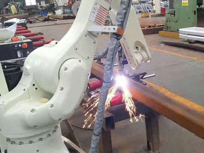
    1. CNC Robotic Beam Cutting Systems

    Engineered for heavy-duty structural processing, CNC robotic beam cutting systems integrate articulated robotic arms with high-power cutting tools (typically plasma or oxy-fuel) to process large-format beams, columns, and structural components. These systems excel in cutting H-beams, I-beams, and box sections made of carbon steel, stainless steel, and aluminum, with cutting thicknesses ranging from 10mm to 300mm and positional accuracy of ±0.2mm/m. Their robust design and automated material handling capabilities make them indispensable in construction, bridge building, and heavy machinery manufacturing, where high-volume processing of structural steel is a core operational requirement.

    2. Plasma Robotic Cutting Systems

    Plasma robotic cutting leverages a high-velocity jet of ionized gas (plasma) generated by an electric arc, which heats and melts conductive materials while expelling molten debris via gas pressure. This technology is distinguished by its high cutting speed (up to 500mm/min for 20mm steel) and ability to process thick materials (up to 150mm for carbon steel), making it ideal for industries such as shipbuilding, offshore engineering, and automotive chassis manufacturing. Modern plasma robotic systems incorporate advanced features such as automatic torch height control (ATHC) and plasma gas optimization, which enhance cut quality by minimizing kerf width (typically 2-5mm) and reducing thermal distortion.

    3. 3D Robot Fiber Laser Cutting Machines

    Fiber laser cutting systems represent the pinnacle of precision cutting technology, utilizing a high-energy fiber laser beam (wavelength: 1064nm) to ablate or melt materials with micron-level accuracy. These machines offer positional repeatability of ±0.03mm and are capable of processing thin to medium-thickness materials (0.1mm to 30mm for metals) with intricate geometries—making them the preferred choice for aerospace component manufacturing (e.g., turbine blades, aircraft fuselage panels), electronics (PCB cutting, micro-component fabrication), and medical device production. The fiber laser’s superior energy density (up to 10^6 W/cm²) ensures minimal heat-affected zones (HAZ), preserving material integrity and reducing post-processing requirements.

    4. Laser Cutting Systems (CO₂ and Fiber)

    Laser cutting systems are classified into CO₂ laser and fiber laser variants, each optimized for specific applications. CO₂ lasers (wavelength: 10.6μm) excel in cutting non-metallic materials such as acrylic, wood, and textiles, with cutting speeds up to 10m/min for thin sheets. Fiber laser systems, by contrast, are tailored for metallic materials, offering higher energy efficiency (up to 30% compared to CO₂ lasers) and lower operational costs. Both technologies are widely adopted in industries requiring high-quality edge finishes, such as jewelry manufacturing (precision metal stamping) and electronics (semiconductor wafer dicing).

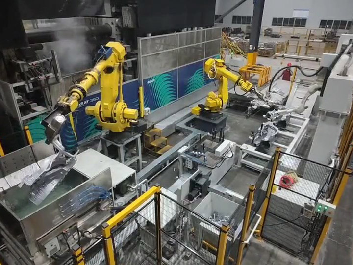
    5. Robotic Cutting Systems (Hybrid Configurations)

    Robotic cutting systems combine the dexterity of multi-axis robotic arms (3-6 axes) with modular cutting tools (plasma, laser, or waterjet), enabling flexible processing of complex workpieces. These hybrid configurations are designed for adaptive manufacturing, where production runs require frequent tool changes or geometry adjustments. Key features include offline programming (OLP) software, collision avoidance systems, and integration with manufacturing execution systems (MES), making them suitable for small-batch production and custom fabrication.

    6. 6-Axis Robotic 3D Laser Cutting Cells

    As the most advanced category of computerized cutting machines, 6-axis robotic 3D laser cutting cells offer six degrees of freedom, enabling simultaneous movement along linear (X, Y, Z) and rotational (A, B, C) axes. This kinematic flexibility allows for cutting complex 3D contours, undercuts, and curved surfaces—critical for aerospace engine components, automotive body-in-white (BIW) structures, and composite material processing. Equipped with high-power fiber lasers (up to 15kW) and real-time vision systems, these cells achieve cutting accuracy of ±0.05mm and are capable of processing materials with hardness up to HRC 60, including titanium alloys and Inconel.

    Critical Selection Criteria for Optimal Performance

    The “best” computerized cutting machine is inherently application-specific, as no single system can excel across all use cases. Below are the key technical, operational, and economic factors to consider when evaluating solutions:

    1. Material Compatibility and Thickness Range

    The primary determinant of machine selection is the type and thickness of materials to be processed. For example:

    – Thick metallic materials (≥50mm): Plasma robotic cutting systems or CNC oxy-fuel cutting machines offer the optimal balance of speed and cost-effectiveness.

    – Thin metals (≤10mm) and intricate designs: 3D robot fiber laser cutting machines deliver superior precision and edge quality.

    – Non-metallic materials (polymers, composites): CO₂ laser cutting systems or waterjet cutting machines are preferred to avoid thermal damage.

    2. Dimensional Accuracy and Tolerance Requirements

    Industries such as aerospace and medical device manufacturing demand ultra-tight tolerances (±0.01mm to ±0.1mm), making 6-axis robotic 3D laser cutting cells or high-precision fiber laser systems the ideal choice. For general metal fabrication (tolerances ±0.5mm), CNC robotic beam cutting or plasma systems provide sufficient accuracy at a lower cost point.

    3. Production Volume and Cycle Time

    High-volume manufacturing environments (e.g., automotive assembly lines) require systems with rapid cutting speeds and automated material handling. CNC robotic beam cutting systems (cycle time reduction of up to 40% vs. manual cutting) and plasma robotic cells are optimized for throughput, while 3D laser systems prioritize precision over raw speed.

    4. Capital and Operational Costs

    Advanced systems such as 6-axis robotic 3D laser cutting cells typically carry a higher initial investment (range: $200,000–$1,000,000) but offer lower operational costs due to energy efficiency and reduced material waste. Budget-constrained operations may opt for entry-level CNC plasma systems ($50,000–$150,000) or refurbished laser cutting machines, provided they meet performance requirements.

    5. Automation Integration and Scalability

    The level of automation required depends on production goals:

    – Fully automated systems (e.g., 6-axis robotic cells with conveyor integration) reduce labor costs by up to 70% and enable 24/7 operation but require higher upfront investment.

    – Semi-automated systems (e.g., standalone CNC laser cutters) are suitable for small-batch production, offering flexibility with lower capital expenditure.

    – Scalability is another critical factor—systems with modular designs (e.g., robotic arms with interchangeable cutting tools) allow for future upgrades to accommodate evolving production needs.

    6. Maintenance and Technical Support

    Reliability and after-sales support are essential for minimizing downtime. Laser-based systems require periodic maintenance (e.g., lens cleaning, laser source calibration) every 500–1,000 operating hours, while plasma systems need electrode replacement every 100–200 hours. Choosing a supplier with a global service network and readily available spare parts is critical for long-term operational efficiency.

    Core Advantages of Computerized Cutting Machines

    The adoption of computerized cutting technology delivers transformative benefits to manufacturing operations, including:

    1. Unmatched Precision and Repeatability

    By eliminating human error and leveraging closed-loop feedback systems, CNC cutting machines achieve consistent dimensional accuracy across thousands of workpieces. This is particularly critical for industries with strict quality control standards (e.g., aerospace OEMs), where even minor deviations can compromise product performance.

    2. Enhanced Production Efficiency

    Automated cutting processes reduce cycle times by 30–60% compared to manual methods, enabling higher throughput and faster time-to-market. Additionally, features such as nest optimization software (which maximizes material utilization) and parallel processing capabilities further enhance operational efficiency.

    3. Exceptional Versatility

    Modern CNC cutting machines can process a wide range of materials and geometries, from simple 2D cuts to complex 3D contours. This versatility allows manufacturers to diversify their product portfolios without investing in multiple specialized tools.

    4. Reduced Material Waste and Sustainability

    Precision cutting minimizes material waste by up to 30% compared to manual methods, reducing raw material costs and environmental impact. Furthermore, energy-efficient technologies (e.g., fiber lasers) lower carbon emissions, aligning with global sustainability initiatives.

    5. Improved Workplace Safety

    Automated systems eliminate the need for operators to work in close proximity to cutting tools, reducing the risk of injuries associated with manual cutting (e.g., lacerations, thermal burns). Advanced safety features—such as interlocked enclosures, emergency stop buttons, and laser safety curtains—further enhance workplace safety.

    Conclusion

    The “best” computerized cutting machine is not a one-size-fits-all solution but rather a technology that aligns with your specific industrial requirements, performance parameters, and budget constraints. For heavy-duty structural processing, CNC robotic beam cutting systems and plasma robotic cells offer optimal speed and durability. For precision-critical applications in aerospace or electronics, 3D robot fiber laser cutting machines or 6-axis robotic 3D laser cutting cells deliver unmatched accuracy. For non-metallic materials, CO₂ laser or waterjet systems are the preferred choices.

    When evaluating options, prioritize technical specifications such as material compatibility, tolerance capabilities, and automation features, while balancing these with long-term operational costs and scalability. By investing in the right computerized cutting machine, manufacturers can unlock significant productivity gains, improve product quality, and maintain a competitive edge in an increasingly demanding global market.

    In the era of Industry 4.0, the integration of CNC cutting systems with IoT (Internet of Things) platforms, AI-driven predictive maintenance, and digital twin technology is poised to further revolutionize material processing—making continuous evaluation of technological advancements a critical component of long-term manufacturing success.

  • What Are Material Handling Robots

    In the era of Industry 4.0, global manufacturing and supply chain ecosystems are undergoing a transformative shift toward automation, digitalization, and intelligent optimization. As the backbone of logistics automation, material handling robots—formally classified as Automated Material Handling Systems (AMHS)—have emerged as critical enablers of operational efficiency, process reliability, and supply chain resilience. These advanced robotic systems redefine the movement, storage, control, and protection of raw materials, work-in-progress (WIP), and finished goods across industrial facilities, warehouses, and distribution centers. By automating labor-intensive, repetitive, and high-risk material handling tasks, they not only address the limitations of manual operations but also unlock new levels of productivity, precision, and scalability for modern enterprises.

    This article provides a technical exploration of material handling robots, covering their core definitions, classification, key technologies, performance benefits, industry applications, and emerging trends. Designed for manufacturing engineers, supply chain managers, and technology procurement professionals, this analysis aims to demystify the technical nuances of these systems while highlighting their strategic value in industrial automation.

    Core Definition and Operational Scope
     

    Material handling robots are programmable, automated systems engineered to execute material-centric tasks with minimal human intervention. Unlike general-purpose industrial robots, they are specialized for optimizing material flow—encompassing functions such as:

    – Precision picking, placing, and sorting of components or finished products;

    – Palletizing (stacking) and depalletizing (unstacking) of bulk goods;

    – Intralogistics transportation between production lines, storage zones, and shipping docks;

    – Automated storage and retrieval (AS/RS) within warehouses or distribution centers;

    – Specialized handling of fragile, hazardous, or high-value materials (e.g., liquids, electronics, pharmaceuticals).

    These robots integrate mechanical engineering, motion control, sensor technology, and software algorithms to adapt to dynamic industrial environments, ensuring consistent performance even in high-volume or complex operational scenarios. Their core value lies in streamlining material flow, reducing bottlenecks, and aligning material handling processes with lean manufacturing principles.

    Classification of Material Handling Robots

    Material handling robots are categorized based on their kinematic design, mobility, and application specificity. Below is a technical breakdown of the most industrially relevant types, including their operational principles, performance parameters, and use cases:

    1. Articulated Material Handling Robots

    Articulated robots are equipped with 4–6 rotational joints (axes) that mimic human arm movement, offering exceptional flexibility for complex material handling tasks. Typically mounted on fixed bases, they are optimized for high-precision picking, placing, and assembly operations in manufacturing environments.

    Key Technical Specifications:

    – Payload capacity: 0.5kg–500kg (industrial-grade models);

    – Repeatability: ±0.01mm–±0.1mm;

    – Reach: 500mm–3,000mm;

    – Integration with end effectors (grippers) for multi-material handling.

    Typical Applications:

    – Automotive manufacturing: Handling engine components, body panels, and fasteners during assembly;

    – Electronics production: Precision placement of circuit boards, semiconductors, and delicate components;

    – Consumer goods: Packaging and sorting of small-to-medium-sized products (e.g., smartphones, cosmetics).

    2. Automated Guided Vehicles (AGVs)

    AGVs are mobile robots that navigate predefined paths using guidance systems such as magnetic tapes, QR codes, or laser triangulation. They are designed for intralogistics transportation, moving heavy loads or bulk materials across warehouses, factories, or distribution centers.

    Key Technical Specifications:

    – Load capacity: 100kg–50,000kg (heavy-duty models);

    – Navigation accuracy: ±10mm–±50mm;

    – Speed: 0.5m/s–2m/s;

    – Safety features: Collision avoidance sensors, emergency stop systems, and compliance with ISO 15085.

    Typical Applications:

    – Warehouse operations: Transporting pallets, bins, and containers between storage racks and packing stations;

    – Manufacturing: Delivering raw materials to production lines and removing finished goods to storage zones;

    – Logistics: Loading and unloading goods from trucks and conveyor systems.

    3. Autonomous Mobile Robots (AMRs)

    AMRs represent the next generation of mobile material handling robots, leveraging advanced navigation technologies (LIDAR, computer vision, SLAM—Simultaneous Localization and Mapping) to navigate dynamically without predefined paths. They can adapt to changes in the environment (e.g., obstacles, rearranged storage racks) and optimize routes in real time.

    Key Technical Specifications:

    – Load capacity: 5kg–1,500kg;

    – Navigation accuracy: ±5mm–±20mm;

    – Autonomy level: Full autonomy (path planning, obstacle avoidance, task prioritization);

    – Integration with warehouse management systems (WMS) and manufacturing execution systems (MES).

    Typical Applications:

    – E-commerce fulfillment centers: Picking and transporting orders to packing stations (e.g., Amazon Robotics Kiva systems);

    – Healthcare: Delivering medical supplies, medications, and equipment within hospitals;

    – Retail: Restocking shelves and transporting inventory between backrooms and sales floors.

    4. Automated Case-Handling Mobile Robots (ACMRs)

    ACMRs are specialized mobile robots designed for handling case-sized loads (e.g., cardboard boxes, plastic crates) in high-throughput warehouse environments. They combine the mobility of AMRs with specialized lifting mechanisms to stack, transport, and sort cases efficiently.

    Key Technical Specifications:

    – Load capacity per case: 10kg–50kg;

    – Stack height: Up to 2.5m;

    – Throughput: 100–300 cases per hour;

    – Compatibility with standard warehouse racking systems (e.g., selective racks, flow racks).

    Typical Applications:

    – Distribution centers: Sorting and transporting cases to shipping lanes;

    – Food and beverage: Handling packaged products between production lines and storage;

    – Retail logistics: Preparing store-ready shipments from regional distribution centers.

    5. Gantry (Cartesian) Robots

    Gantry robots operate along three linear axes (X, Y, Z) within a fixed workspace, offering high precision and load capacity for overhead material handling. They are commonly used in applications requiring repetitive, high-speed picking and placing over large areas.

    Key Technical Specifications:

    – Payload capacity: 1kg–10,000kg;

    – Repeatability: ±0.02mm–±0.1mm;

    – Workspace size: Up to 50m (X-axis), 10m (Y-axis), 3m (Z-axis);

    – Speed: Up to 5m/s (linear movement).

    Typical Applications:

    – Warehouse AS/RS systems: Retrieving and storing pallets or bins from high racks;

    – Automotive: Handling large components (e.g., windshields, seats) during assembly;

    – Packaging: High-speed picking and placing of products into boxes or containers.

    6. Liquid Handling Robots

    Liquid handling robots are specialized systems designed for precise dispensing, mixing, and transferring of liquids in laboratory, pharmaceutical, and biotech environments. They ensure ultra-high precision and reproducibility, critical for scientific research and drug development.

    Key Technical Specifications:

    – Dispensing volume range: 0.1μL–1L;

    – Precision: ±0.1%–±1% of dispensed volume;

    – Throughput: Up to 10,000 samples per hour (high-throughput models);

    – Compatibility with various liquid types (aqueous solutions, solvents, viscous fluids).

    Typical Applications:

    – Pharmaceutical research: Drug discovery and high-throughput screening;

    – Clinical diagnostics: Sample preparation and analysis;

    – Biotechnology: Cell culture media preparation and nucleic acid purification.

    Key Technologies and Components

    Material handling robots rely on a suite of advanced technologies and modular components to deliver precision, reliability, and adaptability. Below is a detailed breakdown of their core technical enablers:

    1. Perception and Navigation Systems

    Perception systems enable robots to interact with their environment, while navigation systems ensure accurate movement:

    – LIDAR (Light Detection and Ranging): Creates 3D maps of the environment for obstacle avoidance and localization, with a range of up to 100m and angular resolution of 0.1°;

    – Machine Vision: Uses cameras and image processing algorithms to identify objects, verify barcodes/QR codes, and ensure precise picking/placing (resolution up to 12MP, frame rate up to 60fps);

    – SLAM Technology: Enables AMRs to build maps in unknown environments and localize themselves in real time, with positioning accuracy of ±5mm;

    – Sensor Fusion: Integrates data from LIDAR, cameras, ultrasonic sensors, and inertial measurement units (IMUs) to enhance environmental awareness and reliability.

    2. End Effectors (Grippers)

    End effectors are the “hands” of material handling robots, customized to handle specific materials and shapes:

    – Mechanical Grippers: Equipped with jaws (parallel, angular, or custom) for gripping solid objects, with clamping forces ranging from 1N to 10,000N;

    – Vacuum Grippers: Use suction cups to handle flat or irregularly shaped objects (e.g., boxes, sheets of metal), with lifting capacities up to 500kg;

    – Magnetic Grippers: Utilize electromagnets or permanent magnets to handle ferrous materials (e.g., steel plates, automotive parts), ideal for high-speed applications;

    – Custom End Effectors: Designed for specialized tasks (e.g., liquid dispensing nozzles, soft grippers for fragile items like glassware or produce).

    3. Control and Software Systems

    Control systems serve as the “brain” of material handling robots, enabling task execution, optimization, and integration:

    – Programmable Logic Controllers (PLCs): Execute low-level control tasks (e.g., motion control, sensor data processing) with response times of <1ms;

    – Robot Operating Systems (ROS): Open-source or proprietary software frameworks for programming, simulation, and integration of robotic components;

    – AI and Machine Learning Algorithms: Optimize path planning, predict maintenance needs, and adapt to dynamic environments (e.g., real-time route adjustment for AMRs);

    – Integration Software: Interfaces with WMS, MES, and enterprise resource planning (ERP) systems to synchronize material handling with production and logistics workflows.

    4. Motion Control Systems

    Motion control systems ensure precise and smooth movement of robotic joints or mobile platforms:

    – Servo Motors: Provide high torque and positional accuracy for articulated robots and gantry systems, with speed control resolution of 0.1rpm;

    – Stepper Motors: Used in low-cost, low-speed applications (e.g., small AGVs), offering precise positioning without feedback;

    – Drive Systems: Include gearboxes, belts, and linear actuators to transmit motion, with efficiency ratings of up to 98%.

    Core Benefits of Material Handling Robots

    The adoption of material handling robots delivers quantifiable technical, operational, and economic benefits to industrial enterprises:

    1. Enhanced Productivity and Throughput

    – 24/7 uninterrupted operation reduces downtime by up to 30% compared to manual labor;

    – High-speed task execution (e.g., AMRs with speeds up to 2m/s, gantry robots with picking rates up to 1,000 cycles per hour) increases throughput by 50–100% in high-volume environments;

    – Automated task prioritization and path optimization minimize idle time, ensuring optimal resource utilization.

    2. Superior Precision and Consistency

    – Repeatability of ±0.01mm–±0.1mm eliminates human error, reducing material waste by 15–25% in precision-critical applications;

    – Consistent handling of materials ensures uniform product quality, particularly in industries such as electronics and pharmaceuticals where tolerances are tight (±0.1mm or less);

    – Machine vision integration enables real-time quality checks during handling, further reducing defect rates.

    3. Cost Reduction and Operational Efficiency

    – Labor cost savings of 30–70% by automating repetitive tasks, with a typical return on investment (ROI) of 1–3 years for industrial-grade systems;

    – Reduced material waste and damage (e.g., <1% damage rate for fragile items) lowers raw material and replacement costs;

    – Energy-efficient designs (e.g., AMRs with low-power motors, regenerative braking) reduce operational energy consumption by 20–30% compared to traditional material handling equipment.

    4. Improved Workplace Safety

    – Elimination of human exposure to high-risk tasks (e.g., lifting heavy loads >25kg, handling hazardous materials, working in extreme temperatures) reduces work-related injuries by up to 80%;

    – Compliance with safety standards (ISO 10218 for industrial robots, ANSI/UL 1740 for AGVs) ensures adherence to global occupational health and safety regulations;

    – Collision avoidance sensors and emergency stop systems prevent accidents in dynamic industrial environments.

    5. Scalability and Flexibility

    – Modular design allows for easy expansion of robot fleets to accommodate growing production volumes;

    – Quick programming and reconfiguration (e.g., teach pendant interfaces, offline programming software) enable adaptation to new products or processes in as little as 1–2 hours;

    – Compatibility with multiple end effectors and material types supports diverse operational needs without significant hardware modifications.

    Industry-Specific Applications

    Material handling robots are tailored to address the unique requirements of diverse industries, with specialized designs and configurations:

    1. Manufacturing

    – Automotive: Articulated robots handle engine components, body panels, and fasteners during assembly; AGVs transport WIP between production lines;

    – Electronics: Precision gantry robots place semiconductors and circuit boards; liquid handling robots dispense solder paste and adhesives;

    – Aerospace: Heavy-duty articulated robots (payload >500kg) handle large structural components (e.g., wings, fuselages); AMRs transport tools and materials in cleanrooms.

    2. Warehousing and Logistics

    – E-commerce: AMRs and ACMRs optimize order fulfillment by picking and transporting items to packing stations, reducing order processing time by 40–60%;

    – Retail Logistics: AGVs and AS/RS systems automate storage and retrieval of inventory, improving space utilization by 30–50%;

    – Third-Party Logistics (3PL): Modular AMR fleets adapt to fluctuating order volumes, ensuring scalability during peak seasons.

    3. Food and Beverage

    – Processing: Hygienic-design robots (stainless steel construction, IP67 rating) handle raw materials and finished products, complying with FDA and EU food safety standards;

    – Packaging: High-speed gantry robots palletize packaged goods, with throughput up to 300 cases per hour;

    – Cold Chain: AMRs designed for low-temperature environments (-20°C to 0°C) transport frozen or refrigerated goods without performance degradation.

    4. Healthcare and Pharmaceuticals

    – Pharmaceuticals: Liquid handling robots dispense reagents and samples for drug discovery, ensuring precision and reproducibility; AGVs transport medications and medical supplies within cleanrooms;

    – Hospitals: AMRs deliver linens, meals, and equipment, reducing staff workload and improving patient care efficiency;

    – Biotechnology: High-throughput liquid handling robots support genomic sequencing and cell culture applications, with dispensing precision of ±0.1μL.

    Challenges and Future Trends

    While material handling robots offer significant benefits, their adoption is not without challenges. However, ongoing technological advancements are addressing these limitations and unlocking new possibilities:

    Key Challenges

    – High Initial Investment: Industrial-grade systems can cost $50,000–$500,000, posing a barrier for small and medium-sized enterprises (SMEs);

    – System Integration Complexity: Integrating robots with legacy WMS/MES systems requires specialized expertise, potentially leading to delays or compatibility issues;

    – Skills Gap: A shortage of trained engineers and technicians capable of programming, maintaining, and troubleshooting robotic systems hinders widespread adoption;

    – Environmental Adaptability: Some robots struggle with harsh environments (e.g., dust, moisture, extreme temperatures) or unstructured spaces (e.g., cluttered warehouses).

    Emerging Trends

    – Collaborative Robots (Cobots): Designed for human-robot collaboration (HRC) under ISO/TS 15066, cobots feature force-torque sensors and safety-rated monitoring, enabling them to work alongside humans in tasks such as picking and packing;

    – AI-Powered Intelligence: Advanced machine learning algorithms optimize path planning, predict equipment failures (predictive maintenance), and enable adaptive handling of variable materials (e.g., deformable packages);

    – Digital Twin Technology: Virtual replicas of material handling systems simulate operations, allowing for offline programming, process optimization, and risk mitigation before deployment;

    – IoT and Connectivity: Industrial IoT (IIoT) integration enables real-time monitoring of robot performance, fleet management, and data-driven decision-making; 5G connectivity supports low-latency communication between robots and central systems;

    – Sustainability: Energy-efficient designs, recyclable materials, and battery technology advancements (e.g., lithium-ion batteries with 8-hour runtime) reduce the environmental footprint of robotic systems.

  • Analysis Of Core Functions, Selection Guide, And Comprehensive Maintenance Strategy For Hydraulic Piston Rods

    As a core power transmission component in hydraulic systems, hydraulic piston rods undertake the critical task of efficiently converting hydraulic energy into mechanical energy. Their reliability directly determines the execution efficiency of scenarios such as excavators, aerospace equipment, and industrial production lines. This article comprehensively analyzes the key usage points of hydraulic piston rods from four dimensions: performance characteristics, selection strategies, application scenarios, and maintenance methods.  

    I. Performance Characteristics and Technical Requirements  

    1. High-Intensity Pressure-Bearing Capacity  

    Manufactured using high-quality alloy steel or precipitation-hardened stainless steel, the tensile strength must reach over 800MPa to handle instantaneous impact loads during construction machinery operations. Piston rods forged from special steel and subjected to heat treatment exhibit a fatigue life increase of more than 40% compared to ordinary materials.  

    2. Composite Protection Treatment Technology  

    The surface undergoes a hard chrome plating process (thickness 0.03-0.05mm) combined with a nano-ceramic coating, achieving a surface hardness of HV900 and maintaining stable protection for over 10 years in corrosive environments such as acid rain and salt spray.  

    3. Precision Machining Standards  

    Diameter tolerance must be controlled within ±0.01mm, and straightness deviation should not exceed 0.05mm/m. The mirror-finish machining process with a surface roughness of Ra ≤ 0.4μm effectively reduces the friction coefficient of cylinder operation by 35%.  

    II. Systematic Selection Strategy  

    1. Load Characteristic Matching  

    For periodic impact loads in construction machinery, 42CrMo alloy steel is recommended; for chemical equipment, 316L stainless steel with PTFE coating is suggested to ensure acid-alkali corrosion resistance. The maximum working load must be calculated, and the rod diameter determined with a safety factor of 1.5-2 times.  

    2. Environmental Adaptation Guidelines  

    – Low-temperature working conditions (-50℃): Use 20CrMnTi alloy with additional low-temperature tempering treatment  

    – High-humidity environments: Configure a double-layer chrome plating + fluorocarbon resin composite protection system  

    – Dust-laden areas: Add a dust seal groove structural design  

    3. Parameter Coordination Design  

    The piston rod stroke should reserve a 10%-15% safety margin, the thread strength at the mounting end should reach over 90% of the rod body strength, and the fit clearance with the guide sleeve should be strictly controlled within the range of 0.05-0.15mm.  

    III. Analysis of Typical Application Scenarios  

    1. Construction Machinery Field  

    In loader boom cylinders, piston rods with diameters of 80-120mm must withstand axial loads exceeding 2000kN. Surface laser cladding technology can extend the wear-resistant life to 10,000 hours.  

    2. Aerospace Systems  

    Piston rods for aircraft landing gear are made of titanium alloy, achieving a strength of 1250MPa through isothermal forging while reducing weight by 40%. Servo actuator piston rods require a roundness error of no more than 0.005mm.  

    3. Intelligent Manufacturing Production Lines  

    Injection molding machine clamping cylinders are equipped with piston rods of 40-60mm diameter, combined with magnetostrictive displacement sensors to achieve a repeat positioning accuracy of ±0.02mm.  

    IV. Lifecycle Maintenance Management  

    1. Daily Monitoring Points  

    Weekly inspection of the rod surface using an electronic endoscope, focusing on detecting longitudinal scratches in the guide belt contact area. When the peeling area of the surface chrome layer exceeds 3%, repair should be performed immediately.  

    2. Scientific Lubrication Scheme  

    Lithium-based grease (NLGI Grade 2) is used for supplementary lubrication every 500 hours. Under extreme working conditions, molybdenum disulfide solid lubricant is recommended to effectively reduce seal aging caused by frictional heat.  

    3. Preventive Replacement Standards  

    Immediate replacement is required under the following conditions:  

    – Rod bending deformation > 0.1mm/m  

    – Surface plating wear depth exceeding 0.02mm  

    – Radial runout exceeding 50% of the tolerance band  

    This technical analysis provides key guidance for improving the reliability of hydraulic systems. Through scientific selection and standardized maintenance, the service life of piston rods can be extended by over 60%. In practical applications, it is recommended to establish equipment files, conduct regular vibration spectrum analysis and oil fluid testing, and implement precise predictive maintenance.

  • High-Precision Honed Tubes: Core Technology Analysis And Industry Application Guide (2025 Latest Edition)

    In the field of precision machining in modern manufacturing, honed tubes, as core functional components, are driving the high-quality development of over 20 industries such as hydraulic systems and construction machinery with their unique technological advantages. These specially processed steel tubes, finished through honing technology, achieve comprehensive improvement in workpiece performance through precise control of inner hole dimensions, surface quality, and cylindricity.  

    I. Core Technological Advantages of Honed Tubes

    1. Micron-Level Dimensional Control  

    Through the integrated application of CNC honing equipment and real-time detection systems, modern honing processes can precisely control inner diameter tolerance within ±0.005mm (H7-H9 accuracy class), with ovality error not exceeding 0.03mm. This precise dimensional matching extends the service life of equipment seals by 2-3 times, completely solving the leakage problems caused by tolerances in traditional steel tubes.  

    2. Super Mirror Finishing Effect  

    Using diamond honing sticks combined with intelligent pressure control systems, the inner wall surface roughness can stably reach Ra0.2-0.4μm. The regular oil storage structure formed by special mesh texture processing technology effectively reduces the friction coefficient of moving parts by over 40%.  

    3. Enhanced Mechanical Properties  

    Through the selection of special steels such as 27SiMn and quenching-tempering processes, the yield strength of honed tubes can reach over 500MPa. Under high-frequency working conditions of 10,000 cycles per minute in heavy machinery, the product maintains stable mechanical performance.  

    II. Analysis of Key Application Scenarios  

    1. Hydraulic System Innovation  

    In the application of hydraulic cylinders for construction machinery, the dimensional stability of high-precision honed tubes enables system pressure to reach 50MPa level. Their ultra-smooth inner walls accelerate hydraulic response speed by 15% and reduce energy loss by 20%, making them the preferred material for hydraulic cylinder manufacturing.  

    2. Automotive Manufacturing Upgrade  

    After adopting honed tubes for engine cylinder blocks, the inner hole roundness deviation is ≤0.01mm, achieving zero-leakage sealing with piston rings. Test data from an automotive enterprise shows that this technology increases engine power density by 12% and reduces exhaust emissions by 8%.  

    3. Intelligent Equipment Transformation  

    Miniature honed tubes (outer diameter 17-23mm) used in industrial robot joint parts ensure transmission system positioning accuracy of ±0.005mm through precise dimensional control, meeting the micron-level motion accuracy requirements of intelligent manufacturing equipment.  

    III. Advanced Guide to Process Flow  

    1. Pretreatment Stage  

    Including 11 pre-processing procedures such as raw material screening and precision cold drawing, ensuring the mechanical properties of the base material comply with ISO 9001 standards. Raw material hardness must be controlled within HRC28-32 to lay the foundation for subsequent processing.  

    2. Multi-Stage Honing Processing  

    Using intelligent honing units for three-step precision grinding: rough honing removes 0.05-0.1mm machining allowance; semi-finish honing improves dimensional accuracy; finish honing achieves nanoscale surface finishing through high-frequency micro-vibration at 6,000 times per minute.  

    3. Quality Assurance System  

    The entire process is equipped with detection equipment such as laser diameter gauges and 3D profilometers, conducting 100% dimensional inspection of honed tubes. Industry-leading enterprises have established big data traceability systems to ensure process parameters of each product are retrievable.  

    IV. Industry Development Trend Forecast  

    According to “China Hydraulics and Pneumatics Industry Development Report (2025)”, the global honed tube market size will exceed 8 billion yuan by the end of 2025, with high-precision products (H7 class and above) accounting for 65% of demand. Three major trends—electrification of construction machinery, high-pressureization of hydraulic systems, and miniaturization of precision manufacturing—will drive honing technology toward intelligence and compounding.  

    It is recommended that equipment manufacturers, when selecting honed tubes, focus on suppliers’ processing accuracy certification (ISO 2768-mK class), material inspection reports (including metallographic analysis), and practical application cases. For special working condition requirements (such as corrosion resistance and high temperature resistance), customized solutions can be requested from manufacturers.

  • What Is an Electric Chain Hoist?

    An electric chain hoist is a compact, mechanical lifting device designed to lift, lower, and move heavy loads horizontally (with a trolley) using an electric motor and a durable steel chain. It is widely used in industrial, commercial, and construction settings for efficient, safe load handling—ideal for both indoor and outdoor applications where manual lifting is impractical or unsafe.

    Core Working Principle

    • Power Source: An electric motor (AC or DC) provides the driving force, eliminating manual labor.
    • Lifting Mechanism: The motor drives a gear system that rotates a chain drum, which winds or unwinds a high-strength steel chain.
    • Load Attachment: A hook (swivel or fixed) at the end of the chain connects to the load, ensuring secure gripping.
    • Control: Operated via a handheld pendant controller or remote control, allowing precise adjustment of lifting/lowering speed and horizontal movement (with a trolley).

    Key Advantages

    • High Load Capacity: Ranges from 0.5 tons to 50+ tons, suitable for light to heavy-duty lifting.
    • Efficiency & Precision: Faster lifting speeds than manual hoists, with smooth, controlled operation for accurate load positioning.
    • Durability: Steel chain and robust motor/gear design withstand harsh environments (dust, moisture, temperature variations).
    • Safety Features: Equipped with overload protection (prevents lifting beyond capacity), emergency stop buttons, and brake systems (prevents load free-fall).
    • Compact & Versatile: Small footprint, easy to install on beams, cranes, or gantries—ideal for tight spaces.

    Typical Applications

    • Factories, warehouses, and workshops (lifting machinery, raw materials, or finished goods).
    • Construction sites (hoisting steel beams, tools, or building materials).
    • Shipping yards and ports (loading/unloading containers or heavy cargo).
    • Automotive repair (lifting engines or vehicle parts).
    • Retail and logistics (stocking heavy items in high shelves).
  • Industrial Electric Chain Hoists for Workstation Lifting

    In the world of industrial lifting, efficiency, safety, and precision are paramount. Whether in manufacturing plants, construction sites, or warehouses, the ability to lift heavy loads quickly and reliably can significantly impact productivity and worker safety. Enter the electric chain hoist—a motorized lifting device that has revolutionized material handling by combining power with ease of operation. 

    Key Features of Electric Chain Hoists

    Modern electric chain hoists come equipped with a range of features designed to enhance performance, safety, and durability. Drawing insights from top manufacturers like Elephant, Tractel, Hitachi, and Weihua, here are some standout features:

    • Heavy-Duty Motors: Designed for high efficiency and low power consumption. For example, Elephant’s FA/FB series offers single and dual-speed motors optimized for industrial use.
    • Power-Off Electromagnetic Brakes: These brakes hold the load securely when power is lost, preventing accidental drops. The safety factor can be three times the rated load.
    • High-Strength Load Chains: Manufactured to international standards (e.g., JIS, ISO), chains are wear-resistant and capable of withstanding heavy-duty use.
    • 360° Swivel Hooks: Allow smooth rotation of loads, reducing the risk of chain twisting or damage.
    • Limit Switches: Automatically stop lifting or lowering to prevent overtravel and potential accidents.
    • Overload Protection Devices: Slip clutch or torque-limiting features prevent the hoist from lifting beyond its rated capacity, protecting both the equipment and operators.
    • Durable Construction: Steel enclosures and corrosion-resistant components ensure longevity even in harsh environments.
    • Compact and Lightweight Design: Facilitates installation in confined spaces without sacrificing lifting power.
    • Control Options: Pendant controls with IP65 protection, wireless remotes, and simple plug-in wiring for ease of use and maintenance.

    Advantages of Electric Chain Hoists Over Manual Alternatives

    Electric chain hoists offer several advantages that make them the preferred choice in many industrial applications:

    1. Reduced Operator Fatigue: Motorized lifting eliminates the need for strenuous manual effort, minimizing the risk of injury.
    2. Higher Load Capacities: Electric hoists can handle loads ranging from a few hundred kilograms to several tons, far exceeding manual hoist capabilities.
    3. Precision and Control: Dual-speed motors allow for smooth, accurate positioning, essential in delicate assembly or maintenance tasks.
    4. Consistent Performance: Unlike human operators, electric hoists maintain the same efficiency and reliability over hundreds of lifting cycles.
    5. Integration with Trolleys and Cranes: Electric hoists can be combined with motorized trolleys (e.g., Elephant’s MAS, MAF, MB series) for horizontal movement, enhancing workflow flexibility.
    6. Safety Enhancements: Features like overload protection, limit switches, and electromagnetic brakes reduce the risk of accidents.
    7. Energy Efficiency: Modern designs consume less power while delivering robust performance.
  • How do I choose the right V-grooving machine for my workshop?

    Core Decision Framework (Prioritized)

    1. Clarify Your Core Requirements First

    • Material Specs:
      • Type: Stainless steel/aluminum/copper/composites (carbide tools required for hard metals)
      • Thickness: <3mm (basic models suffice); 3-6mm (heavy-duty vertical/hydraulic); >6mm (specialized CNC)
    • Production Scale:
      • Low-volume (occasional jobs): Manual/semi-automatic (cost-effective)
      • High-volume (mass production): CNC with auto-loading/unloading (reduces labor, ensures consistency)
      • Batch Size: Small batches (flexible manual); large batches (CNC with program storage)
    • Precision Needs:
      • General fabrication (e.g., HVAC): ±0.05mm (mechanical/hydraulic)
      • High-precision (e.g., architecture/elevators): ±0.01-0.03mm (CNC servo-driven)
    • Workpiece Size:
      • Oversized sheets (≥3m length): Horizontal (large worktable)
      • Standard sheets (<2m): Vertical (smaller footprint, better precision)

    Verify Critical Technical Parameters

    • Precision & Repeatability: Ensure error margin aligns with your industry (e.g., ±0.01mm for architectural metalwork)
    • Cutting Speed: ≥60m/min for high-volume; ≥120m/min for mass production (CNC models)
    • Clamping System: Hydraulic (secure for thick materials) vs. manual (suitable for thin sheets)
    • Tool Compatibility: Interchangeable cutters (30°/45°/60°) for versatile groove angles
    • Sheet Size Capacity: Match maximum length/width to your typical workpieces (avoid over/under-sizing)

    https://www.jianmeng.com/grooving_machine.html

  • Metal Grooving and V-Grooving Machinery

    What is Metal Grooving?

    Metal grooving is a manufacturing process that creates recessed channels (grooves) in metal surfaces for various purposes:

    • Facilitating precise bending with smaller radii
    • Enabling complex shape formation
    • Improving structural integrity
    • Aiding assembly alignment

    V-Grooving: The Core Technology

    V-grooving is a specialized form of metal grooving that creates V-shaped channels in metal sheets before bending. This process significantly enhances bending capabilities, allowing:

    • Sharp, clean bends with minimal radius
    • Reduced bending force requirements
    • Consistent results across different thicknesses

    How it works: A V-grooving machine precisely cuts a V-shaped groove into the metal sheet at the bending point. After grooving, the material can be bent using a press brake with standard tools to achieve complex shapes with minimal distortion.

    Key Components & Working Principles

    Main Components:

    • Cutting Head: Equipped with specialized carbide or high-speed steel tooling
    • Worktable: Adjustable platform for material positioning
    • Drive System: Moves cutting head along predefined paths (servo-driven in CNC models)
    • Clamping System: Secures workpiece during operation (hydraulic in advanced models)
    • Control Panel: Interface for programming (CNC) or manual adjustments

    Operation Steps:

    1. Material is clamped securely on the worktable
    2. Cutting parameters (depth, angle, speed) are set
    3. The cutting head moves along the groove path, removing material to form the V-shape
    4. After grooving, the workpiece is bent using a press brake along the weakened groove line

    Applications Across Industries

    Primary Applications:

    • Architectural Decoration: Creating sleek metal panels for facades, ceilings, and interior designs
    • Elevator Manufacturing: Producing precise, seamless elevator cabins and doors
    • Cabinetry & Furniture: Enabling complex metal furniture designs with sharp edges
    • Appliance Manufacturing: Forging precise bends in appliance housings
    • Security Doors: Creating strong, aesthetically pleasing door frames
    • HVAC Ducting: Facilitating smooth bends in air conditioning systems

    Advantages of V-Grooving Technology

    1. Superior Bending: Achieves bend radii as small as 0.1mm, eliminating unsightly large arcs
    2. Versatility: Works with various materials (stainless steel, aluminum, copper, composites) up to 6mm thick
    3. Cost Efficiency:
      • Reduces required press brake tonnage
      • Allows use of standard bending tools
      • Minimizes material waste
      • Increases production speed
    4. Quality Consistency: Ensures uniform results across production runs
    5. Design Freedom: Enables complex shapes that traditional bending cannot achieve
  • Applications Of Single Head Power Hammers

    Single head power hammers are critical, high-performance assets in metalworking, leveraging controlled impact energy to shape, forge, and refine metallic workpieces. Unlike manual hammers or multi-head systems (optimized for high-volume standardization), single head designs prioritize flexibility and precision control—making them indispensable for medium-batch production, custom fabrication, and artisanal metalwork. This analysis explores their technical fundamentals, core capabilities, industrial applications, and selection criteria, with a focus on how their design (e.g., variable speed drives, pneumatic-hydraulic systems) addresses diverse metalworking challenges.  

    1. Technical Overview of Single Head Power Hammers  

    At their core, single head power hammers convert mechanical or fluid power into repetitive, adjustable-impact force via a single forging head (weight: 50–5,000 kg). Their operation is defined by three key parameters:  

    – Impact Energy: Measured in joules (J), ranging from 500 J (light-duty for sheet metal) to 10,000 J (heavy-duty for bulk forging). This determines the maximum material thickness (e.g., 500 J for 10 mm低碳钢; 5,000 J for 50 mm alloy steel) and deformation intensity.  

    – Blow Frequency: 60–300 blows per minute (bpm), adjustable to match material ductility (e.g., low bpm for brittle metals like cast iron; high bpm for ductile metals like copper).  

    – Stroke Length: 50–300 mm, controlling the distance the hammer head travels to generate impact—critical for deep forging vs. surface refinement.  

    These machines are typically classified by their drive system: pneumatic, hydraulic, or hybrid (pneumatic-hydraulic), each tailored to specific load requirements.  

    2. Core Technical Features & Functional Advantages  

    Single head power hammers distinguish themselves through design innovations that enhance control, efficiency, and operator safety. Below is a technical breakdown of their key features:  

    2.1 Variable Speed Drive Systems  

    Equipped with AC variable frequency drives (VFDs) or hydraulic flow regulators, these systems enable precise adjustment of blow frequency (60–300 bpm) and impact force. Technical benefits include:  

    – Material Compatibility: Low speeds (60–120 bpm) for high-strength alloys (e.g., 4140 chromoly steel) to prevent cracking; high speeds (180–300 bpm) for soft metals (e.g., aluminum 6061) to ensure uniform deformation.  

    – Process Tuning: Fine-tune speed for specific tasks (e.g., 80 bpm for hot forging of automotive crankshaft blanks; 250 bpm for cold sizing of knife blades).  

    2.2 Pneumatic-Hydraulic Hybrid Drive (Common in Industrial Models)  

    Most modern single head hammers use a hybrid system—compressed air (0.6–0.8 MPa) to lift the hammer head, and hydraulic pressure to control impact velocity. This design offers:  

    – Energy Efficiency: 30–40% lower power consumption than fully mechanical drives, as pneumatic lift reduces hydraulic load.  

    – Soft Impact Capability: Hydraulic dampers modulate impact force for delicate tasks (e.g., surface planishing of sheet metal), avoiding over-deformation.  

    2.3 Self-Contained Unit Design  

    Integrates all critical components (drive system, oil reservoir, air compressor, control panel) into a single frame, eliminating the need for external infrastructure. Key technical benefits:  

    – Compact Footprint: Ideal for small-to-medium workshops (floor space: 2–5 m² for light-duty models).  

    – Simplified Maintenance: Centralized access to filters, seals, and lubrication points; typical preventive maintenance intervals: 500 operating hours for hydraulic oil changes, 600 hours for pneumatic seal replacement.  

    2.4 Safety & Control Systems  

    Compliant with ISO 13849-1 (functional safety) and OSHA standards, including:  

    – Light Curtains: Stop hammer operation if hands enter the forging zone.  

    – Emergency Stop (E-Stop): Hardwired cutoff for drive systems, with response time <0.1 seconds.  

    – Load Monitoring: Sensors detect overloads (e.g., excessive force on hardened metals) and trigger automatic shutdown to prevent component damage.  

    3. Industrial & Artisanal Applications  

    Single head power hammers excel in applications requiring customization and variable process parameters—from heavy industrial forging to high-precision artisanal work. Below are their primary use cases, with technical details and industry examples:  

    3.1 Hot Forging of Structural & Mechanical Components  

    In automotive, aerospace, and construction machinery, single head hammers are used for hot forging (temperature: 800–1,200°C for steel) of load-bearing parts:  

    – Automotive: Forging connecting rod blanks (material: 4140 steel) and differential gears. Impact energy of 3,000–5,000 J ensures full die penetration, while variable speed (80–120 bpm) prevents grain coarsening.  

    – Aerospace: Forming titanium alloy (Ti-6Al-4V) brackets for aircraft landing gear. Hybrid drives deliver controlled, low-velocity impacts to avoid titanium’s sensitivity to rapid deformation.  

    – Construction Machinery: Shaping bucket teeth (material: 1045 medium-carbon steel) via open-die forging. The single head’s adjustable stroke (150–250 mm) accommodates varying tooth sizes.  

    3.2 Sheet Metal Forming & Refinement  

    For industries like automotive body manufacturing, HVAC, and custom metal fabrication, single head hammers handle sheet metal (thickness: 1–10 mm) tasks:  

    – Shape Correction: Cold planishing (room temperature) of welded sheet metal panels (e.g., automotive door skins) to eliminate warping. Blow frequency of 200–250 bpm ensures uniform surface stress relief.  

    – Complex Curving: Forming mild steel (1018) sheets into architectural components (e.g., curved handrails). Variable impact force (500–1,000 J) prevents wrinkling while achieving tight radii (minimum R=5 mm).  

    – Edge Flanging: Creating 90° flanges on sheet metal enclosures (e.g., electrical junction boxes). Hydraulic control maintains ±0.2 mm flange height tolerance.  

    3.3 Artisanal Metalwork & Specialty Fabrication  

    Blacksmiths, knife makers, and custom metal artists rely on single head hammers for precision and creativity:  

    – Knife & Blade Forging: Shaping high-carbon steel (e.g., 1095, S30V) into blades. Low impact energy (300–800 J) and slow speeds (60–100 bpm) allow for controlled tapering and heat treat retention.  

    – Custom Ironwork: Forging decorative elements (e.g., door knockers, railings) from mild steel. The single head’s maneuverability enables intricate details (e.g., scrollwork) that multi-head machines cannot replicate.  

    – Musical Instrument Manufacturing: Forming brass (C26000) or copper (C11000) into trumpet bells or cymbal blanks. Pneumatic drives deliver soft, consistent impacts to preserve acoustic properties.  

    3.4 Cold Sizing & Finishing  

    In precision manufacturing (e.g., fasteners, medical devices), single head hammers perform cold sizing (room temperature) to refine dimensions:  

    – Fastener Production: Sizing hex bolts (material: 1022 steel) to meet ISO 4014 tolerance standards (±0.1 mm for bolt head height). Impact energy of 800–1,200 J ensures full thread formation without cracking.  

    – Medical Implants: Finishing titanium bone plates. Low-force impacts (200–500 J) and sterile lubricants (food-grade mineral oil) maintain biocompatibility.  

    4. Performance Advantages Over Traditional Methods  

    Single head power hammers outperform manual hammers and specialized machines in key metrics:  

    | Metric               | Single Head Power Hammer                          | Manual Hammer                                  | Multi-Head Power Hammer                      |  

    |—————————|——————————————————-|—————————————————-|————————————————–|  

    | Productivity          | 300–500% faster (e.g., 20 connecting rod blanks/hour) | 1–2 blanks/hour (operator-dependent)                | 50+ blanks/hour (but limited to standard parts)  |  

    | Precision             | ±0.2 mm dimensional tolerance; uniform grain flow     | ±1–2 mm tolerance; inconsistent deformation         | ±0.1 mm tolerance (but inflexible for custom work)|  

    | Material Versatility  | Handles 1–50 mm thicknesses (steel, aluminum, titanium)| Limited to <10 mm soft metals                       | Optimized for 5–20 mm standardized materials     |  

    | Operator Safety       | Reduces repetitive strain injuries (RSIs) by 80%;Light Curtains | High RSI risk; no automated safety features         | Similar safety features but larger footprint      |  

    5. Technical Selection Criteria  

    When choosing a single head power hammer, align specifications with application requirements using these technical parameters:  

    5.1 Impact Energy & Material Compatibility  

    – Light-Duty (500–1,500 J): For sheet metal (<10 mm) and artisanal work (knives,铁艺).  

    – Medium-Duty (1,500–5,000 J): For automotive components (connecting rods, gears) and structural steel (<30 mm).  

    – Heavy-Duty (5,000–10,000 J): For bulk forging (construction machinery parts, aerospace brackets) in thick metals (>30 mm).  

    5.2 Drive System Type  

    – Pneumatic: Best for light-to-medium tasks (low noise, 70–85 dB); ideal for workshops with compressed air infrastructure.  

    – Hydraulic: Higher impact force for heavy-duty forging; requires oil cooling systems for continuous use.  

    – Hybrid (Pneumatic-Hydraulic): Balanced efficiency and force; optimal for mixed applications (e.g., forging + sheet metal work).  

    5.3 Durability & Component Materials  

    – Hammer Head: H13 hot work tool steel for heat resistance (up to 600°C) in hot forging.  

    – Hammer Rod: 4140 chromoly steel (tensile strength: 800 MPa) for impact resistance.  

    – Frame: Welded A36 steel (yield strength: 250 MPa) with vibration damping to reduce machine wear.  

    5.4 Maintenance Accessibility  

    – Wear Parts: Choose models with quick-change pneumatic seals and hydraulic filters (e.g., spin-on filters for 5-minute replacement).  

    – Lubrication: Automatic grease systems (e.g., 12-point distribution) reduce manual maintenance time by 50%.  

  • Understanding The Basics Of Sheet Metal Shrinker Stretchers Machine

    Sheet metal shrinker stretchers are specialized contouring equipment designed for precision plastic deformation of sheet metal—enabling the creation of complex curves, radii, and compound shapes without material removal (cutting) or joining (welding). Unlike bending tools (which form linear angles) or English wheels (which stretch large flat surfaces), shrinker stretchers excel at localized, controlled deformation—making them indispensable for industries requiring tight-tolerance contouring, such as automotive restoration, aerospace subassembly, and custom metal fabrication. This technical overview breaks down their operating principles, equipment classification, applications, and best practices to establish a foundational understanding of their role in modern metalworking.  

    1. Technical Principles of Shrinker Stretchers

    At their core, shrinker stretchers manipulate sheet metal via two complementary deformation mechanisms—compressive shrinking and tensile stretching—using interchangeable jaw assemblies. The process relies on localized force application to avoid global material failure (e.g., cracking, wrinkling) while preserving structural integrity.  

    1.1 Shrinking Mechanism  

    Shrinking reduces the sheet metal’s cross-sectional area and surface length via controlled plastic compression:  

    – Jaw Design: Shrinker jaws feature serrated or grooved surfaces (to grip metal without slippage) and a tapered profile that concentrates force on a narrow material strip (typically 5–15 mm wide).  

    – Force Application: When activated, jaws clamp the metal and draw it inward, compressing the material along the contour line. This shortens the metal’s length, causing it to curve outward (e.g., forming a convex radius on a car fender).  

    – Material Limits: Effective for ductile metals (e.g., low-carbon steel 1018, aluminum 3003) with elongation values >15%; unsuitable for brittle alloys (e.g., cast iron, high-carbon steel >0.8% C) due to cracking risk.  

    1.2 Stretching Mechanism  

    Stretching increases the sheet metal’s surface area and length via localized tensile force:  

    – Jaw Design: Stretcher jaws use a broader, smoother contact surface (to distribute force evenly) and a cam-driven mechanism that pulls the metal outward as jaws open.  

    – Force Application: Jaws grip the metal and expand laterally, stretching the material along the contour line. This lengthens the metal’s length, causing it to curve inward (e.g., forming a concave radius on an aircraft cowl panel).  

    – Key Consideration: Stretching must be incremental (1–2 mm per pass) to avoid necking (localized thinning >20%), which weakens the material.  

    2. Classification of Shrinker Stretchers  

    Equipment is categorized by power source and jaw configuration, each tailored to specific workloads, material thicknesses, and precision requirements.  

    2.1 By Power Source  

    | Type               | Operation Principle                                                                 | Technical Specs                                                                 | Ideal Applications                          |  

    |————————-|—————————————————————————————–|————————————————————————————-|————————————————-|  

    | Manual (Mechanical) | Lever-driven (mechanical advantage: 15:1 to 25:1) to generate clamping force.           | Max material thickness: 1.2 mm (steel), 2 mm (aluminum); Force output: 2–5 kN.       | Hobby projects, small-batch custom work, repairs. |  

    | Pneumatic           | Compressed air (0.6–0.8 MPa) drives a piston to actuate jaws; adjustable pressure.      | Max material thickness: 3 mm (steel), 4 mm (aluminum); Force output: 8–15 kN.        | Medium-volume fabrication (e.g., automotive shops). |  

    | Hydraulic           | Hydraulic cylinder (10–30 MPa) delivers high, consistent force; pressure-regulated.     | Max material thickness: 6 mm (steel), 8 mm (aluminum); Force output: 20–50 kN.       | Heavy-duty industrial use (e.g., aerospace subassemblies). |  

    2.2 By Jaw Configuration  

    Jaw design dictates the tool’s ability to handle different material sizes and contour types:  

    – Standard Jaws: 25–50 mm wide; for general-purpose contouring (e.g., 90° radii on sheet metal brackets).  

    – Deep-Throat Jaws: 75–150 mm throat depth; for shaping large sheets or accessing hard-to-reach areas (e.g., inner fender wells).  

    – Radius-Specific Jaws: Pre-shaped to create fixed radii (e.g., R=10 mm, R=25 mm); eliminates trial-and-error for repetitive parts.  

    – Interchangeable Jaw Sets: Quick-change (1–2 minute swap) between shrinker/stretcher jaws; ideal for mixed-contour projects (e.g., combining convex/concave curves on a single part).  

    3. Core Industrial Applications  

    Shrinker stretchers are valued for their ability to produce non-linear, tight-tolerance shapes that other tools cannot achieve efficiently. Below are their most critical use cases, with technical requirements:  

    3.1 Automotive Restoration & Customization  

    – Tasks: Shaping fender flares, door skins, and hood contours; repairing rust-damaged panels (e.g., restoring 1960s muscle cars).  

    – Technical Requirements: Tolerance ±0.5 mm for panel alignment; compatibility with mild steel (18–22 gauge) and aluminum (16–18 gauge).  

    – Example: Using a pneumatic shrinker with deep-throat jaws to form a 30° convex curve on a 1.5 mm steel fender, ensuring alignment with the original chassis.  

    3.2 Aerospace Subassembly  

    – Tasks: Fabricating ductwork, cowl panels, and interior structural components (e.g., aircraft seat frames).  

    – Technical Requirements: Tolerance ±0.1 mm (per aerospace standard AS9100); compatibility with aluminum alloys (6061-T6, 2024-T3) and titanium (Ti-6Al-4V, thin-gauge).  

    – Example: Hydraulic stretchers with radius-specific jaws (R=15 mm) to form concave curves on 2 mm 6061-T6 aluminum ductwork, avoiding material thinning >5%.  

    3.3 Custom Metal Fabrication  

    – Tasks: Creating architectural elements (e.g., curved railings, decorative panels), industrial enclosures, and marine components (e.g., boat hull trim).  

    – Technical Requirements: Versatility across materials (steel, aluminum, copper); ability to handle variable thicknesses (0.8–4 mm).  

    – Example: Manual shrinker-stretcher with interchangeable jaws to shape 1 mm copper into a custom light fixture, combining convex and concave curves.  

    4. Technical Operation Best Practices  

    Achieving consistent, high-quality results requires adherence to process controls and material-specific techniques:  

    4.1 Pre-Operation Setup  

    1. Material Preparation:  

       – Deburr all edges (to prevent jaw damage); mark contour lines with a scribing tool (using a template for repeatability).  

       – Test a scrap piece of the same material/thickness to calibrate force (e.g., 5 kN for 1 mm aluminum, 12 kN for 3 mm steel).  

    2. Jaw Selection:  

       – Use serrated jaws for thick/soft metals (e.g., aluminum) to prevent slippage; smooth jaws for thin/hard metals (e.g., stainless steel) to avoid surface marring.  

       – Align jaws parallel to the contour line (±1°) to ensure uniform deformation.  

    4.2 In-Process Controls  

    1. Incremental Deformation:  

       – Apply 1–2 mm of shrinkage/stretching per pass; avoid over-deforming (e.g., shrinking >5 mm in one pass causes wrinkling).  

       – Rotate the part 5–10° between passes for compound curves (e.g., a “S” shape), ensuring force is distributed evenly.  

    2. Defect Correction:  

       – Wrinkling (shrinking): Reduce jaw overlap by 20% and apply lighter force; stretch adjacent areas to redistribute material.  

       – Necking (stretching): Reduce force by 30% and use shorter passes; shrink the opposite side to restore thickness.  

    4.3 Post-Operation Inspection  

    – Measure contour accuracy with a radius gauge or coordinate measuring machine (CMM) to verify tolerance compliance.  

    – Check for material defects (e.g., cracks, thinning) using a thickness gauge (target: <10% thickness loss for structural parts).  

    5. Maintenance & Calibration Protocols  

    Prolonging equipment lifespan and ensuring consistent performance requires proactive maintenance:  

    5.1 Routine Maintenance (Per 50 Operating Hours)  

    – Cleaning: Remove metal shavings/debris from jaws using a wire brush; wipe down hydraulic/pneumatic lines to check for leaks.  

    – Lubrication: Apply lithium-based grease to pivot points (jaw hinges, lever connections); use pneumatic tool oil (ISO VG 32) for air-driven components.  

    5.2 Preventive Maintenance (Per 500 Operating Hours)  

    – Jaw Inspection: Check for tooth wear (replace jaws if teeth are flattened >30%); verify jaw alignment with a straightedge (adjust if misalignment >0.2 mm).  

    – Power System Service:  

      – Pneumatic: Replace air filters and check pressure regulators (calibrate to 0.7 MPa).  

      – Hydraulic: Change oil (ISO VG 46 hydraulic oil) and replace filters; test pressure relief valves (ensure they trigger at 110% of max rated force).  

    5.3 Calibration (Quarterly)  

    – Use a force gauge to verify output (e.g., ensure a 10 kN hydraulic stretcher delivers 9.5–10.5 kN); adjust pressure regulators if off-spec.  

    – Calibrate jaw parallelism using a feeler gauge (gap <0.05 mm between jaws at full closure).  

    6. Equipment Selection Criteria  

    When choosing a shrinker stretcher, align specifications with your application’s technical needs:  

    1. Material Thickness & Type: Select a model with force output matching your max material (e.g., 15 kN for 3 mm steel, 5 kN for 1 mm aluminum).  

    2. Precision Requirements: Manual models for ±1 mm tolerance; pneumatic/hydraulic for ±0.1–0.5 mm.  

    3. Production Volume: Manual for <10 parts/week; pneumatic for 10–50 parts/week; hydraulic for >50 parts/week.  

    4. Workspace Constraints: Manual models (weight: 5–15 kg) for benchtop use; pneumatic/hydraulic (weight: 50–200 kg) for floor-mounted setups.